Yacht Spars and Rigging Guide
Yacht Spars and Rigging Guide. A yacht’s mast, boom, standing rigging and sail-handling poles form one structural system that transfers sail loads into the hull. The mast carries compression, the shrouds and stays control its position, the boom carries mainsail and sheet loads, and the poles hold headsails or spinnakers in their required position. None of these components operates independently. A worn terminal can place bending load into a stay, an incorrectly tuned shroud can distort the mast, and a damaged boom or pole fitting can fail when a sail refills after rolling or an accidental gybe.
The skipper must inspect this equipment as structural machinery rather than as permanent deck furniture. Stainless steel can develop fatigue and crevice corrosion while retaining a polished surface. Synthetic fibre can lose strength through chafe, heat, creep and incorrect terminations. Aluminium spars can corrode beneath stainless fittings, while carbon spars can suffer impact damage that is not obvious from the surface. This guide introduces the separate technical pages covering standing rigging, terminals, masts, booms, spinnaker poles and whisker poles.
Yacht Rigging Guide - Synthetic Fibre Running Rigging
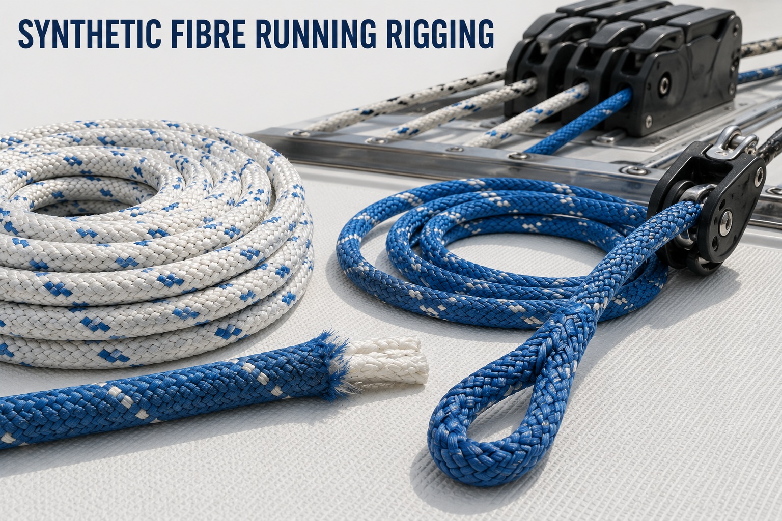
The synthetic fibre running rigging page covers HMPE-core halyards, sheets, reefing lines, control lines, soft shackles and structural strops. These ropes provide reduced elongation and lower weight, but they must be matched to the load and the yacht’s deck equipment. A rope with sufficient published breaking strength can still be unsuitable if it slips in a clutch, overheats on a winch or bends around an undersized sheave. The page explains fibre grades, rope covers, clutch compatibility, winch heat, stripped halyards, soft shackles and inspection requirements. Use this section when selecting or replacing lines that move, pass through deck equipment or are adjusted during sailing. Synthetic Fibre Rigging for Yachts and the Yacht Synthetic Running Rigging Inspection Guide
Yacht Spars and Rigging
Guide - Synthetic Standing Rigging
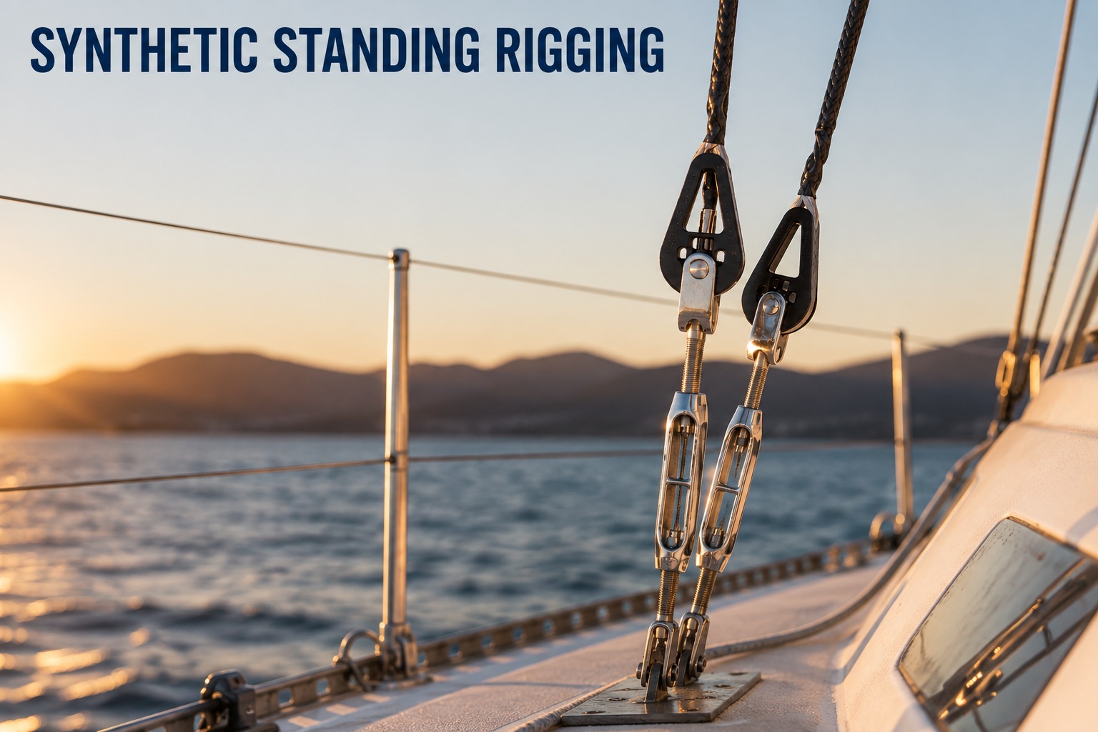
Synthetic standing rigging uses HMPE or proprietary composite systems in place of stainless-steel wire or rod. The main operational advantage is reduced weight aloft and the elimination of stainless-steel corrosion. The complete stay includes the rope or cable, splice, terminal, thimble, deadeye, tensioning system and mast and chainplate fittings. Creep, constructional bedding, bend radius and chafe control form part of the structural design. The synthetic standing rigging page explains how to compare wire, rod, HMPE and composite systems. It also covers rig-load calculations, conversion limits, commissioning, mast tuning, insurance acceptance and offshore repairability. Read more about Synthetic Standing Rigging for Cruising Yachts
Yacht Synthetic Rigging
Inspection and Maintenance
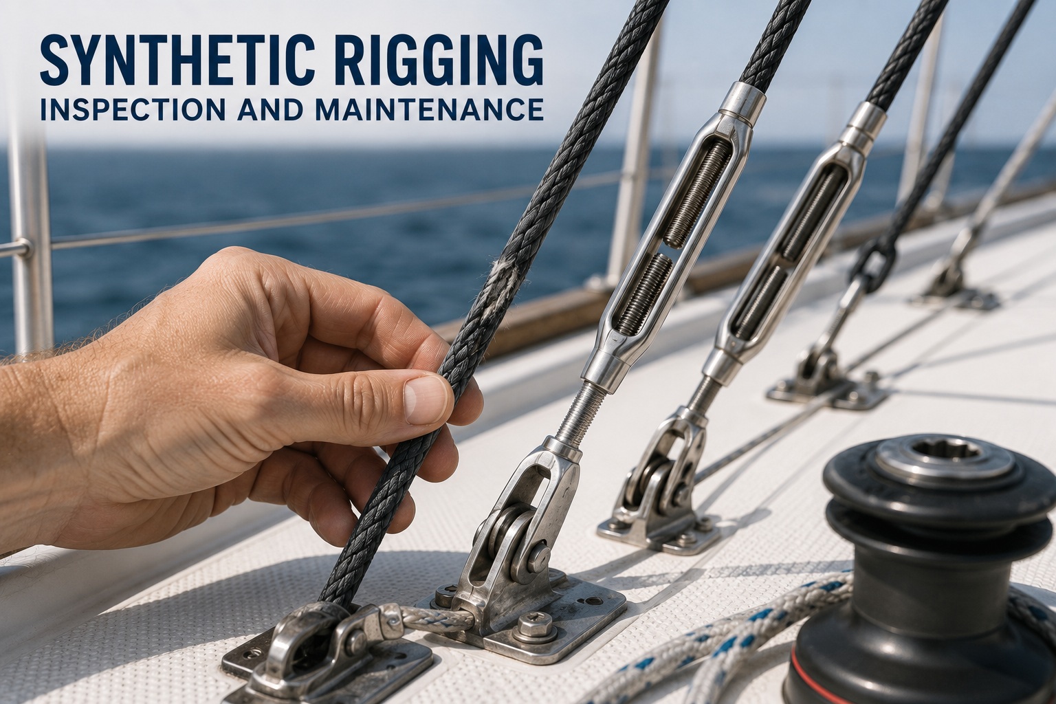
Synthetic rigging does not rust, but it remains subject to ageing and damage. The inspection page explains how to identify chafe, heat damage, ultraviolet degradation, pulled fibres, splice movement and loss of rig tension. Running rigging requires close inspection at sheaves, clutches, winches and cover transitions. Standing rigging requires inspection at thimbles, deadeyes, lashings, spreaders and mast terminals. The skipper must retain records identifying the product, installation date, splice method and service history. Surface appearance alone cannot confirm remaining strength, particularly where damage is concealed beneath a cover or inside a termination. Read more about Yacht Synthetic Standing Rigging Inspection Guide
Yacht Spars and Rigging
Guide - Stainless Steel Standing
Rigging
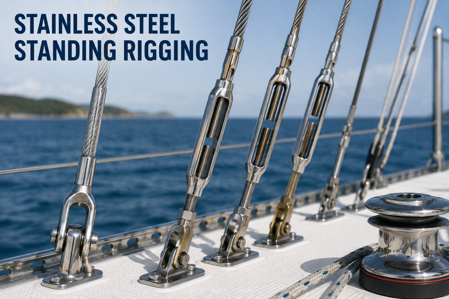
Stainless steel standing rigging remains standard equipment on cruising yachts because it provides stable dimensions, established terminal systems and broad repair support. The stainless standing rigging page explains 1x19 wire, compact-strand wire, flexible wire constructions, shroud and stay functions, rig loads, corrosion and fatigue. It also covers forestays concealed inside furling systems, adjustable backstays, inner forestays and chainplate load paths. The skipper must recognise that stainless steel is corrosion resistant rather than corrosion proof. Crevice corrosion can develop inside swages, beneath covers and at chainplate penetrations where salt water remains trapped. Stainless Steel Standing Rigging for Yachts
Yacht Spars and Rigging
Guide - Stainless Steel Terminals
and Installation
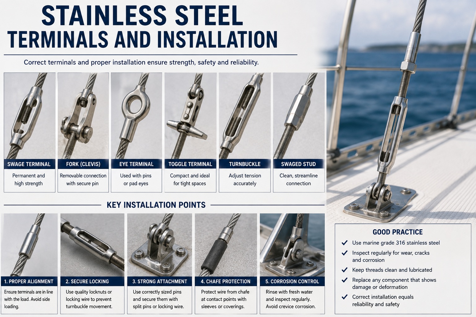
A standing-rigging wire is only as reliable as its terminals and installation. The terminal page covers machine swages, mechanical terminals, turnbuckles, toggles, clevis pins, T-terminals and stemballs. Each fitting must match the wire diameter and strand construction. Turnbuckles must retain adequate thread engagement, toggles must allow articulation, and pins must carry load across a full round bearing surface. The page also explains mast stepping, stay measurement, terminal alignment, initial rig tension and sailing commissioning. It defines conditions such as jaw spreading, thread galling, pin wear, elongated holes and partly seated mast terminals so less experienced skippers can identify them during inspection. Yacht Stainless Steel Rigging Terminals and Installation
Yacht Spars and Rigging
Guide - Stainless Steel Rigging
Inspection and Replacement
The inspection and replacement page covers many defects from broken strands, kinked wire, cracked swages, worn pins, seized toggles, chainplate corrosion and unexplained rig-tension changes. A materially worn pin contains a groove, flattened bearing area, reduced diameter or bending. A worn turnbuckle can have damaged threads, spread forks, elongated holes or bent studs. These conditions alter the way the component carries load and require replacement rather than polishing or adjustment. The page also addresses replacement intervals, partial versus complete rerigs, reuse of hardware, insurer requirements and emergency support after a stay failure. Stainless Steel Rigging Inspection and Replacement
Why not get a copy of my book The Marine and Electrical and Electronics Bible 4th Edition. In Australia order a copy through Boat Books. UK based boats can Order Here. US based boats can get the US edition Order Here. Marine systems are my profession so let me help you.

Yacht Spars and Rigging
Guide - Masts
The mast page treats the mast as a compression structure extending from the masthead to the mast step and hull support. It covers keel-stepped and deck-stepped masts, aluminium corrosion, permanent bends, mast pumping, spreader roots, spreader tips, halyard sheaves, mast terminals and internal wiring. Changes in mast shape or rig tension can indicate mast-step settlement, compression-post movement or structural damage. The page also explains when mast removal is required to inspect the heel, step, concealed fittings and internal systems. How to Inspect a Sailing Yacht Masts.
Yacht Spars and Rigging
Guide - Booms
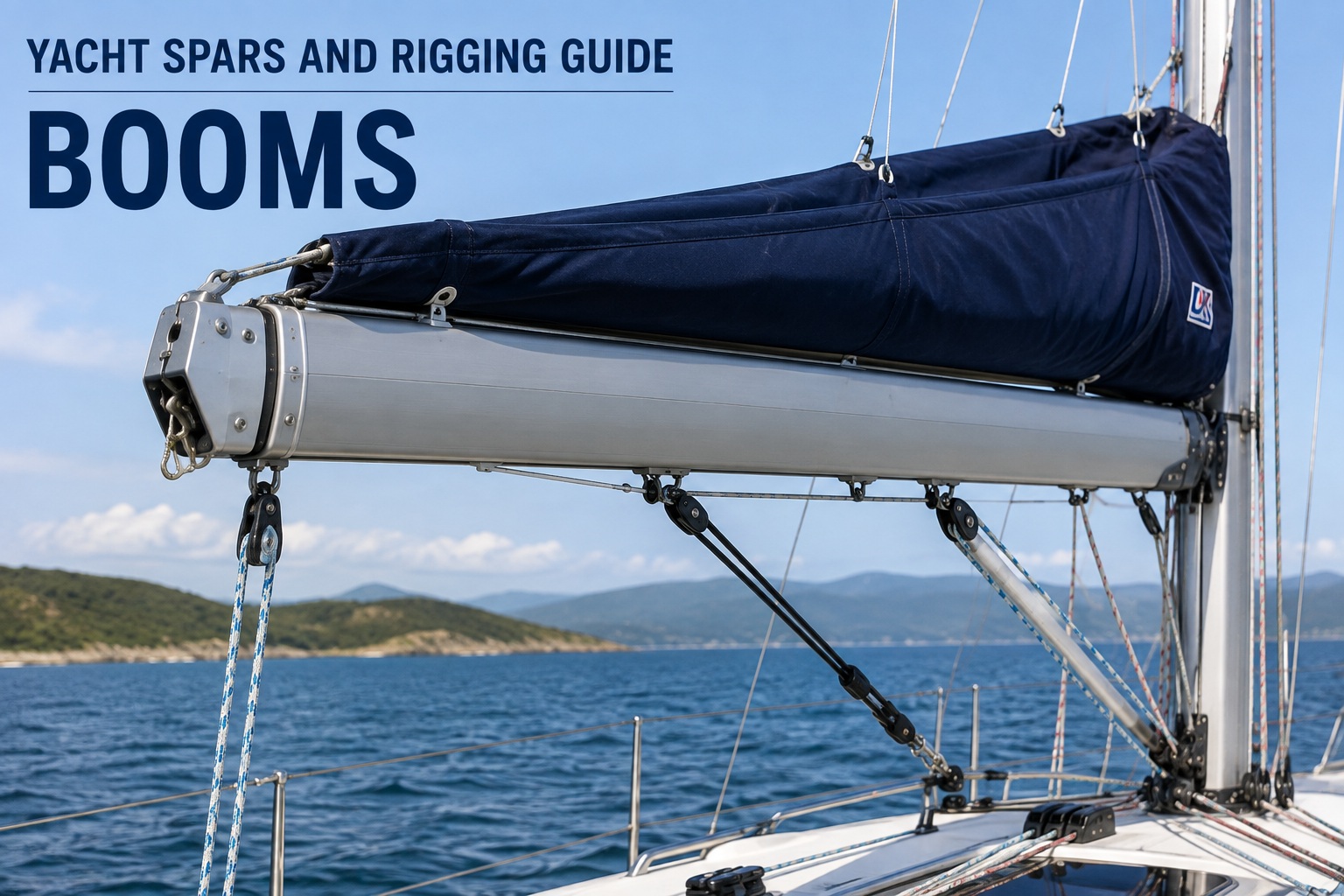
The boom carries mainsail, mainsheet, vang, reefing and outhaul loads. The highest loads are concentrated at the gooseneck, vang fitting, mainsheet attachment and boom end. The boom page explains gooseneck-pin wear, jaw spreading, elongated holes, aluminium corrosion, reefing-system faults and internal tackle problems. It also covers preventer loads and inspection after an accidental gybe. A permanent bend, crease, crack or corroded high-load attachment requires assessment before the boom returns to service. Sailing Yacht Booms Inspection and Maintenance


Yacht Spars and Rigging
Guide - Spinnaker Poles
A spinnaker pole carries compression between the afterguy and mast fitting. It also depends on the uphaul, downhaul, bridles, mast track and pole car. The spinnaker pole page covers tube dents, damaged end fittings, seized triggers, mast-track wear, pole height and end-for-end or dip-pole gybing. A dent or crease reduces resistance to buckling. A trigger that fails to lock or release can prevent the crew controlling the pole during a gybe. Sailing yacht Spinnaker Poles Operation and Inspection
Yacht Spars and Rigging
Guide - Whisker Poles
A whisker pole supports a poled-out headsail and reduces repeated sail collapse when sailing downwind. The whisker pole page covers fixed and telescopic poles, tube-overlap limits, twist locks, pin locks, end fittings, mast rings and control lines. Telescopic poles lose structural capacity as overlap decreases and must not be extended beyond their marked limits. Rolling and sail refill can shock-load the pole even when the headsail is smaller than a spinnaker. Sailing yacht Whisker Pole Operation and Inspection
Yacht Spars and Rigging
Guide - Summary
Masts, booms, poles and standing rigging must be maintained as one connected structural system. Wire, fibre, terminals and spars have different failure modes, but each requires known specifications, physical inspection and documented service history. The skipper must investigate corrosion, cracking, permanent deformation, unexpected movement and changes in rig tension before applying further sailing load. These linked pages provide the detailed operating, inspection and replacement guidance required to identify defects before they develop into loss of sail control, spar failure or dismasting Yacht Spars and Rigging Guide for all you need to know.