Stainless Steel
Standing Rigging for Yachts
Stainless steel standing rigging for yachts. Stainless steel standing rigging supports the mast, controls mast alignment and transfers sailing loads into the hull through the chainplates and supporting structure. The complete system includes the cap shrouds, lower and intermediate shrouds, forestay, backstay, inner forestay, baby stay, terminals, turnbuckles, toggles, clevis pins, mast fittings and chainplates. Failure of any one component can release part of the mast support or allow the mast to move outside its designed geometry.
The skipper must treat standing rigging as one structural load path rather than a collection of separate wires. Wire diameter, strand construction, terminal type, articulation, rig tension, mast geometry and chainplate alignment determine how the load passes from the mast into the hull. Stainless steel is widely understood and can be repaired in most established cruising regions, but it remains subject to fatigue, crevice corrosion, stress concentration and concealed terminal damage. A polished surface does not confirm that the complete system is structurally sound.
Stainless Steel
Standing Rigging for Yachts - Function
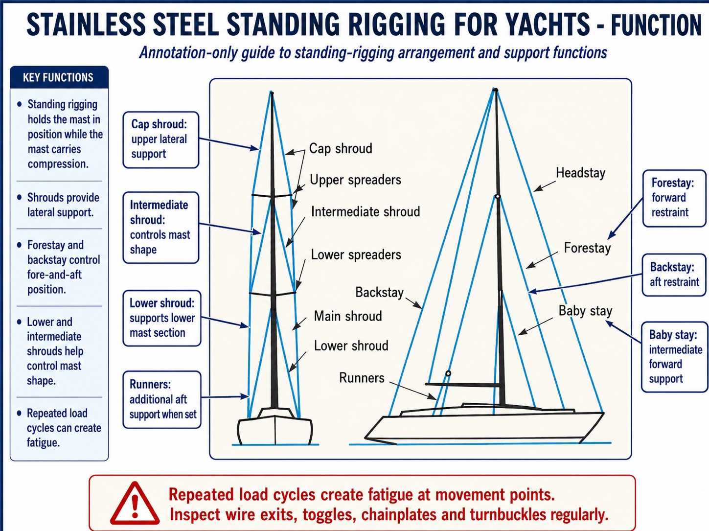
Standing rigging holds the mast in its designed position while the mast carries compression generated by sail load and rig tension. The shrouds prevent lateral movement, the forestay and backstay control fore-and-aft movement, and the lower and intermediate shrouds control mast shape between the deck and masthead.
Rigging loads are not constant, they are dynamic. The load changes every time the yacht tacks, gybes, pitches into a wave or rolls downwind. A headsail collapsing and refilling can apply a rapid load increase to the forestay. An accidental gybe can shock-load the backstay and upper shrouds. Hull flexing can also alter the distance between chainplates and mast terminals.
Repeated load cycles create metal fatigue even when the rig has never been loaded close to its published breaking strength. Fatigue normally begins where movement is concentrated, including the point where wire exits a terminal, where a toggle has seized, or where a chainplate and turnbuckle are out of alignment.
Stainless Steel
Standing Rigging for Yachts - Wire
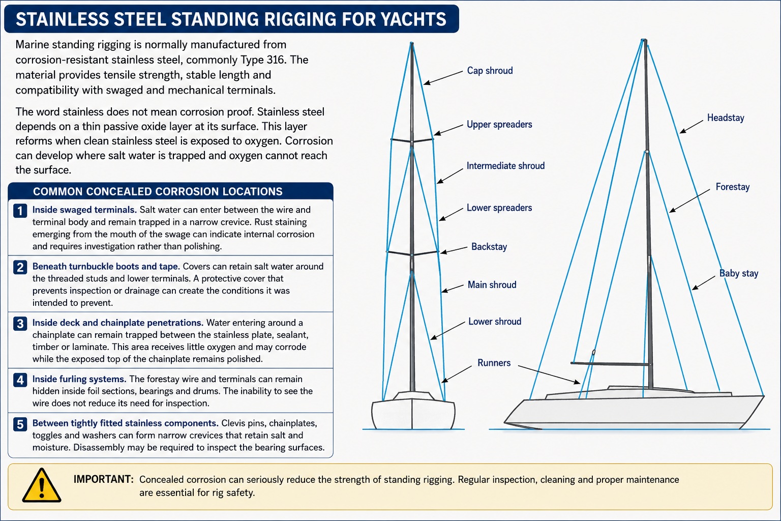
Marine standing rigging is normally manufactured from corrosion-resistant stainless steel, commonly Type 316. The material provides tensile strength, stable length and compatibility with swaged and mechanical terminals.
The word stainless does not mean corrosion proof. Stainless steel depends on a thin passive oxide layer at its surface. This layer reforms when clean stainless steel is exposed to oxygen. Corrosion can develop where salt water is trapped and oxygen cannot reach the surface. Common concealed corrosion locations include the following:
- Inside swaged terminals. Salt water can enter between the wire and terminal body and remain trapped in a narrow crevice. Rust staining emerging from the mouth of the swage can indicate internal corrosion and requires investigation rather than polishing.
- Beneath turnbuckle boots and tape. Covers can retain salt water around the threaded studs and lower terminals. A protective cover that prevents inspection or drainage can create the conditions it was intended to prevent.
- Inside deck and chainplate penetrations. Water entering around a chainplate can remain trapped between the stainless plate, sealant, timber or laminate. This area receives little oxygen and may corrode while the exposed top of the chainplate remains polished.
- Inside furling systems. The forestay wire and terminals can remain hidden inside foil sections, bearings and drums. The inability to see the wire does not reduce its need for inspection.
- Between tightly fitted stainless components. Clevis pins, chainplates, toggles and washers can form narrow crevices that retain salt and moisture. Disassembly may be required to inspect the bearing surfaces.
Stainless Steel
Standing Rigging for Yachts - 1x19 Stainless Wire
The standard construction for yacht standing rigging is 1x19 wire. It consists of a central wire surrounded by layers of additional wires to create a stiff cable with low extension. The stiffness makes 1x19 suitable for fixed shrouds and stays. It is not intended to bend repeatedly around small sheaves or form tight loops. Repeated bending causes individual wires to work against each other and concentrates fatigue at the bend.
A 1x19 stay must leave each terminal in the same direction as the applied load. A wire that bends immediately above a swage indicates that the terminal lacks articulation or that the connected fittings are misaligned. The wire must not be expected to act as the flexible joint. A kink in 1x19 wire permanently disturbs the strand arrangement. Straightening the cable does not restore the original load sharing between the individual wires. A visibly kinked structural stay requires replacement rather than cosmetic straightening.
Stainless Steel
Standing Rigging for Yachts - Compact-Strand Wire
Compact-strand wire uses shaped or compressed strands to reduce the spaces between the individual wires. This creates a smoother cable and can provide a higher strength or lower extension for a given diameter. The smaller diameter can reduce rigging weight and windage. This may provide a useful advantage on performance yachts, but it does not make compact strand a direct substitute for conventional 1x19 wire.
The terminal must be approved for the compact-strand construction. A mechanical cone designed for conventional 1x19 may not separate and grip compacted strands correctly. A swaging procedure may also require different tooling or dimensions. The skipper must retain records identifying the wire construction. A future rigger cannot safely select replacement terminals by measuring diameter alone.
Stainless Steel
Standing Rigging for Yachts - Flexible Wire Construction
Flexible wire constructions such as 7x7 and 7x19 contain several bundles of smaller wires. They tolerate repeated bending better than 1x19 but normally stretch more and have different strength characteristics. These constructions are used where the wire must move around a sheave or bend repeatedly, including steering cables, control cables and some flexible backstay arrangements.
Do not replace a fixed 1x19 shroud with flexible wire merely because the diameter is the same. The change affects strength, stiffness, elongation, fatigue behaviour and terminal compatibility. Do not use standing-rigging wire for steering or control systems that require repeated bending. The stiff construction will fatigue where it passes around sheaves.
Stainless Steel
Standing Rigging for Yachts - Material and Product Identification
All polished stainless wire does not have the same composition, construction or strength. The skipper must know what has been installed. The standing-rigging record must identify the following criteria:
- The wire manufacturer and product. This allows replacement wire and terminals to be matched to the original specification rather than selected by appearance.
- The stainless-steel grade. The material grade confirms that the wire is intended for marine structural use and provides a basis for assessing corrosion resistance.
- The strand construction. The record must state whether the cable is conventional 1x19, compact strand or another construction because the terminal system depends on this information.
- The nominal diameter. Diameter is required for load calculations, terminal selection and future inspection, but it does not identify the wire strength by itself.
- The published minimum breaking load. This figure provides one part of the structural specification but must be considered together with working load, fatigue and terminal efficiency.
Do not install unidentified stainless cable as a structural stay. General-purpose architectural or industrial wire may have a different construction, material grade or quality-control standard.
Stainless Steel
Standing Rigging for Yachts - Rigging Loads
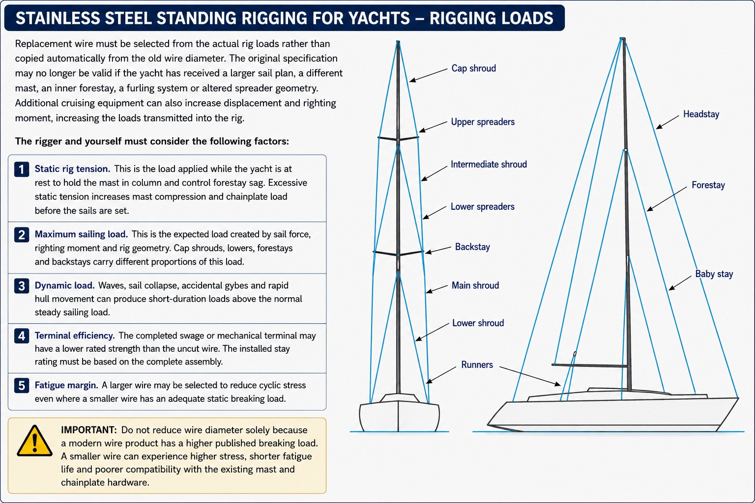
Replacement wire must be selected from the actual rig loads rather than copied automatically from the old wire diameter. The original specification may no longer be valid if the yacht has received a larger sail plan, a different mast, an inner forestay, a furling system or altered spreader geometry. Additional cruising equipment can also increase displacement and righting moment, increasing the loads transmitted into the rig. The rigger and yourself must consider the following factors:
- Static rig tension. This is the load applied while the yacht is at rest to hold the mast in column and control forestay sag. Excessive static tension increases mast compression and chainplate load before the sails are set.
- Maximum sailing load. This is the expected load created by sail force, righting moment and rig geometry. Cap shrouds, lowers, forestays and backstays carry different proportions of this load.
- Dynamic load. Waves, sail collapse, accidental gybes and rapid hull movement can produce short-duration loads above the normal steady sailing load.
- Terminal efficiency. The completed swage or mechanical terminal may have a lower rated strength than the uncut wire. The installed stay rating must be based on the complete assembly.
- Fatigue margin. A larger wire may be selected to reduce cyclic stress even where a smaller wire has an adequate static breaking load.
Do not reduce wire diameter solely because a modern wire product has a higher published breaking load. A smaller wire can experience higher stress, shorter fatigue life and poorer compatibility with the existing mast and chainplate hardware.
Stainless Steel
Standing Rigging for Yachts - Cap Shrouds
Cap shrouds support the upper mast and normally run from the masthead or upper spreader area to the deck chainplates. They carry continuous static tension and a large proportion of the lateral sailing load. The windward cap shroud becomes more heavily loaded as the yacht heels, while the leeward shroud unloads. The skipper must examine the following:
- Wire condition at the spreader tip. The shroud must remain seated in the spreader-end fitting without being pinched, bent or allowed to move across a sharp edge.
- Terminal alignment at the mast. The upper terminal must align with the stay direction. A terminal bearing against one edge of its socket indicates side loading.
- Turnbuckle alignment at deck level. The turnbuckle and chainplate must lie in the same plane as the shroud. A threaded stud leaning sideways is being subjected to bending as well as tension.
- Leeward-shroud behaviour under sail. A leeward shroud may lose some tension, but it must not whip, hammer against the mast or become completely uncontrolled. Excessive slack can indicate inadequate rig tension or incorrect load distribution.
Do not tighten a cap shroud without checking mast alignment and the opposing shroud. A change on one side alters mast compression and lateral position.
Stainless Steel
Standing Rigging for Yachts - Lower and Intermediate Shrouds
Lower shrouds control the lower mast and can also establish fore-and-aft mast bend. Intermediate shrouds support the mast between spreader levels. Forward and aft lowers carry different loads. Forward lowers normally oppose aft mast movement, while aft lowers oppose forward movement and can influence prebend. Inline lowers mainly control lateral mast position. Inspect for the following conditions:
- Unequal tension between paired lowers. One lower carrying substantially more load than its opposite can pull the mast out of column and concentrate load at the chainplate or mast tang.
- A lateral bend between spreaders. Sight up the mast track. A bend to port or starboard indicates that the intermediate or lower shrouds are not balanced.
- Fore-and-aft mast distortion. Excessive tightening of a forward or aft lower can create a local bend rather than the smooth prebend intended by the mast design.
- Loose terminals at the mast. T-terminals and tangs must remain fully seated and must not move inside worn mast slots.
Do not tune the lowers by counting visible turnbuckle threads. Equal thread exposure does not confirm equal stay load or correct mast shape
Stainless Steel
Standing Rigging for Yachts - Forestay
The forestay supports the forward rig and carries the luff load of the headsail. Its tension controls forestay sag and therefore affects headsail shape. On a furling yacht, much of the forestay is concealed. The skipper must not assume that the wire remains serviceable because the furler rotates. Specific inspection concerns include the following points:
- The upper forestay terminal. It is exposed to mast movement and can fatigue if the toggle or stemball does not articulate freely.
- The lower terminal and turnbuckle. These parts may remain inside the furling drum where salt water and dirt can accumulate.
- Foil connector movement. A loose or damaged foil connector can rub against the wire and produce local wear.
- Furler bearing condition. A seized bearing can introduce torsional or bending loads into the forestay.
- Forestay adjustment. A concealed turnbuckle must retain adequate thread engagement and must not be left unlocked after adjustment.
The furling system may need to be dismantled to inspect or replace the forestay. Difficulty of access is not a reason to extend an unknown service life.
Stainless Steel
Standing Rigging for Yachts - Backstay
The backstay opposes forestay load and supports the masthead. A fixed backstay remains under static tension. An adjustable backstay changes forestay tension and mast bend during sailing. Make the following inspections:
- The wire immediately above an adjuster. A hydraulic cylinder or mechanical adjuster can restrict articulation and cause the wire to bend at the terminal exit.
- Adjuster pins and forks. Pins must remain straight and forks must remain parallel. Wear grooves or spread jaws indicate uneven bearing.
- Hydraulic pressure retention. A cylinder that slowly loses pressure reduces backstay tension and may indicate a leaking seal or internal defect.
- Mechanical locking. A screw or tackle adjuster must remain locked at the selected load and must not unwind during vibration.
Do not apply more backstay load than the mast, chainplates and rigging were designed to carry.
Stainless Steel
Standing Rigging for Yachts - Inner Forestays and Baby Stays
An inner forestay may support a staysail and reduce the unsupported length of the mast. A babystay normally controls the lower mast and contributes to prebend. Removable stays require a positive deck attachment and a tensioning system that can reach the design load. The following points require inspection:
- Highfield levers and pelican hooks. The lever must close fully and the locking pin must prevent accidental release. A partially closed lever may carry the load on a small part of the mechanism.
- Deck attachment movement. The fitting must not lift, distort the deck or open a crack in the surrounding laminate when the stay is tensioned.
- Stored-stay chafe. A removable stay secured alongside the mast must not strike the mast or rub against wiring, sails or halyards.
- Terminal alignment. The stay must enter the deck and mast fittings without being forced sideways when tensioned.
Do not fit or tension an inner stay to a deck fitting unless the supporting structure below deck has been verified.
Stainless Steel
Standing Rigging for Yachts - Rigging Weight and Windage
Stainless wire contributes weight aloft and aerodynamic drag. The operational significance depends on wire diameter, mast height, number of stays, yacht displacement and righting moment. A lighter rig reduces the yacht’s vertical centre of gravity and mast inertia, but cruising decisions must also account for repairability, insurer acceptance and service access. Stainless wire remains a practical choice where the following applies:
- Local repair support is required. Wire, terminals and turnbuckles can be sourced in more cruising ports than proprietary composite rigging components.
- Survey familiarity matters. Surveyors and insurers generally understand conventional wire systems and their replacement records.
- Stable dimensions are required. Stainless wire has predictable elastic extension and does not experience polymer creep.
- Existing hardware is designed for wire. Mast tangs, chainplates and furling systems may already be configured around conventional terminals and pin sizes.
The weight penalty must be assessed against the yacht’s actual operating requirements rather than treated as an automatic reason to convert to another material.
Your Complete
Onboard Repair Resource
Why not get a copy of my book The Marine and Electrical and Electronics Bible 4th Edition. In Australia order a copy through Boat Books. UK based boats can Order Here. US based boats can get the US edition Order Here. Marine systems are my profession so let me help you.

Stainless Steel
Standing Rigging for Yachts - Corrosion
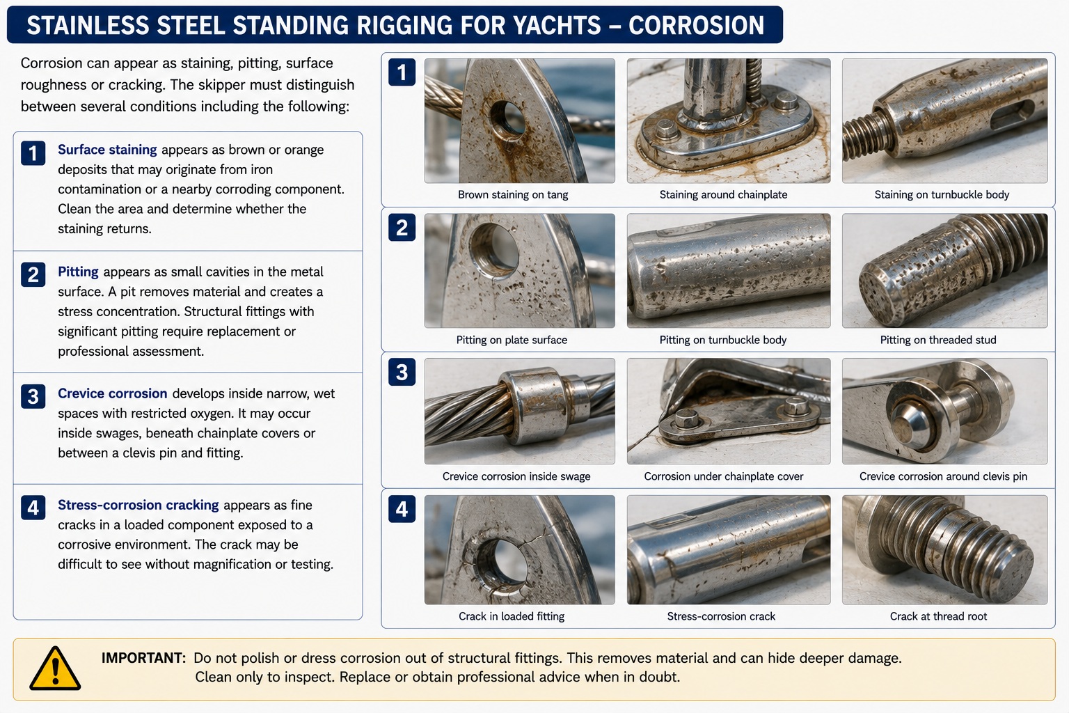
Corrosion can appear as staining, pitting, surface roughness or cracking. The skipper must distinguish between several conditions including the following:
- Surface staining appears as brown or orange deposits that may originate from iron contamination or a nearby corroding component. Clean the area and determine whether the staining returns.
- Pitting appears as small cavities in the metal surface. A pit removes material and creates a stress concentration. Structural fittings with significant pitting require replacement or professional assessment.
- Crevice corrosion develops inside narrow, wet spaces with restricted oxygen. It may occur inside swages, beneath chainplate covers or between a clevis pin and fitting.
- Stress-corrosion cracking appears as fine cracks in a loaded component exposed to a corrosive environment. The crack may be difficult to see without magnification or testing.
Do not polish away corrosion products before recording where they originated. The stain location can identify a concealed defect.
Stainless Steel
Standing Rigging for Yachts - Fatigue
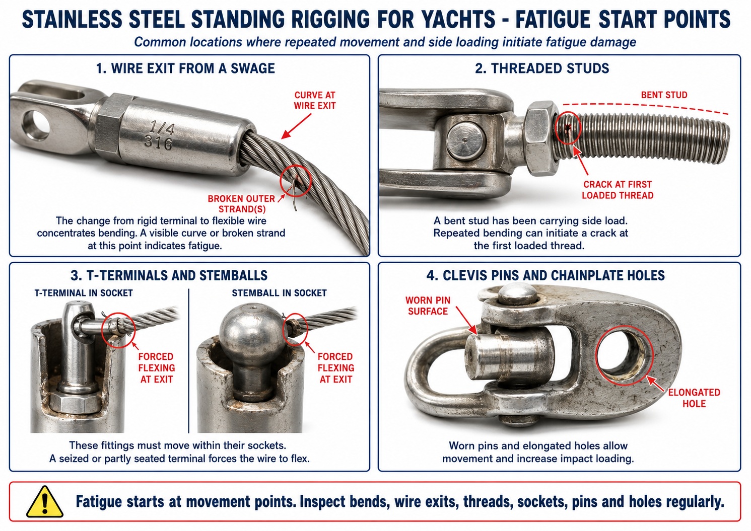
Fatigue damage develops through repeated loading rather than one overload event. Critical locations include the following:
- The wire exit from a swage. The change from rigid terminal to flexible wire concentrates bending. A visible curve or broken strand at this point indicates fatigue.
- Threaded studs. A bent stud has been carrying side load. Repeated bending can initiate a crack at the first loaded thread.
- T-terminals and stemballs. These fittings must move within their sockets. A seized or partly seated terminal forces the wire to flex.
- Clevis pins and chainplate holes. Worn pins and elongated holes allow movement and increase impact loading.
- Spreader tips. A loose or sharp spreader-end fitting can bend or abrade the shroud during every mast movement.
Fatigue life cannot be confirmed from a breaking-load test performed when the wire was new. Service history and inspection remain essential.
Stainless Steel
Standing Rigging for Yachts - Articulation and Alignment
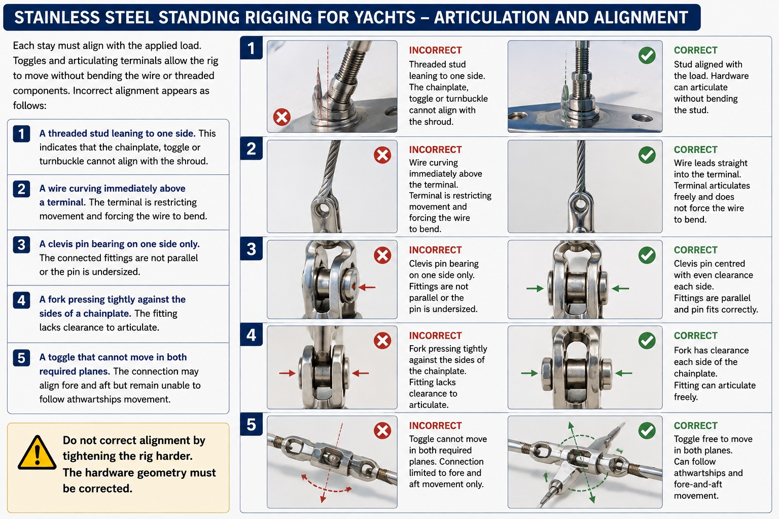
Each stay must align with the applied load. Toggles and articulating terminals allow the rig to move without bending the wire or threaded components. Incorrect alignment appears as follows:
- A threaded stud leaning to one side. This indicates that the chainplate, toggle or turnbuckle cannot align with the shroud.
- A wire curving immediately above a terminal. The terminal is restricting movement and forcing the wire to bend.
- A clevis pin bearing on one side only. The connected fittings are not parallel or the pin is undersized.
- A fork pressing tightly against the sides of a chainplate. The fitting lacks clearance to articulate.
- A toggle that cannot move in both required planes. The connection may align fore and aft but remain unable to follow athwartships movement.
Do not correct alignment by tightening the rig harder. The hardware geometry must be corrected.
Stainless Steel
Standing Rigging for Yachts - Chainplates
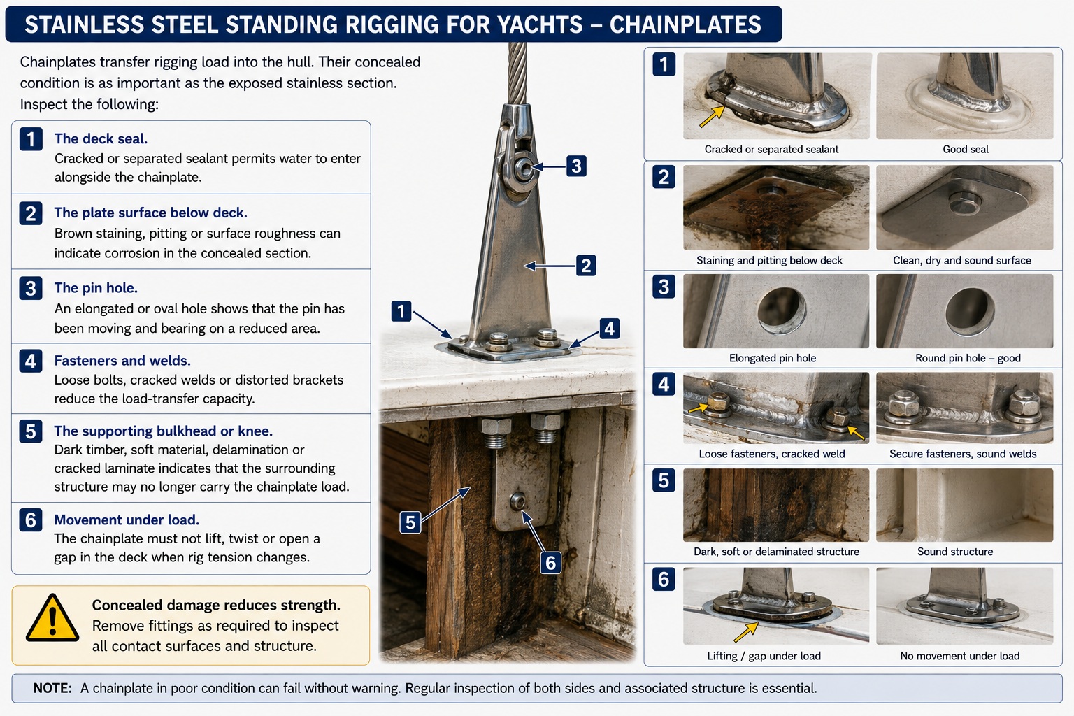
Chainplates transfer rigging load into the hull. Their concealed condition is as important as the exposed stainless section. Inspect the following:
- The deck seal. Cracked or separated sealant permits water to enter alongside the chainplate.
- The plate surface below deck. Brown staining, pitting or surface roughness can indicate corrosion in the concealed section.
- The pin hole. An elongated or oval hole shows that the pin has been moving and bearing on a reduced area.
- Fasteners and welds. Loose bolts, cracked welds or distorted brackets reduce the load-transfer capacity.
- The supporting bulkhead or knee. Dark timber, soft material, delamination or cracked laminate indicates that the surrounding structure may no longer carry the chainplate load.
- Movement under load. The chainplate must not lift, twist or open a gap in the deck when rig tension changes.
Do not fit new standing rigging to chainplates whose concealed condition has not been established.


Stainless Steel
Standing Rigging for Yachts - Selecting Stainless Standing Rigging
Stainless wire remains suitable for yachts requiring conventional hardware, broad repair availability and predictable rig dimensions. Before ordering a replacement rig, record the wire product, construction, diameter, terminal types, pin dimensions, turnbuckle threads, loaded lengths and chainplate geometry.
Do not automatically retain old turnbuckles, toggles or pins because they appear polished. These parts have experienced the same load cycles and environment as the wire. A standing-rigging replacement is complete only when the wire, terminals, adjustment system, mast fittings and chainplates have been assessed as one structural system.
Stainless Steel
Standing Rigging for Yachts - Summary
Stainless steel standing rigging remains a practical system for cruising yachts because it combines structural strength, stable length, established hardware and broad repair support. Its reliability depends on correct wire construction, calculated loads, aligned terminals, adequate articulation and sound chainplates. Stainless steel can fail through fatigue and concealed corrosion while the exposed wire remains polished. The skipper must understand each shroud and stay as part of one load path extending from the mast into the hull and must maintain records identifying the wire, terminals, installation date and operating history. Stainless Steel Standing Rigging for Yachts for all you need to know.