How Different Bilge Pump Float
Switches Work
How Different Bilge Pump Float Switches Work. Bilge pump float switches provide automatic control of the bilge pump by responding to changes in water level. As bilge water rises, a buoyant float or lever moves and operates an internal switching mechanism, closing the electrical circuit and starting the pump. When the water level falls, the switch returns to its lower position, opens the circuit and stops the pump. This automatic operation is essential when a vessel is unattended or when water enters the bilge faster than the crew notices.
Although float switches perform the same basic function, their internal operating methods vary. Common designs use a rolling metal ball, a mercury-tilt capsule, a magnetic reed switch or a lever-operated microswitch. Each type has different current-handling capability, mounting requirements, failure modes and maintenance needs. Understanding these differences helps the skipper choose an appropriate switch, install it correctly and identify faults before automatic bilge protection is lost.
How
Different Bilge Pump Float Switches Work
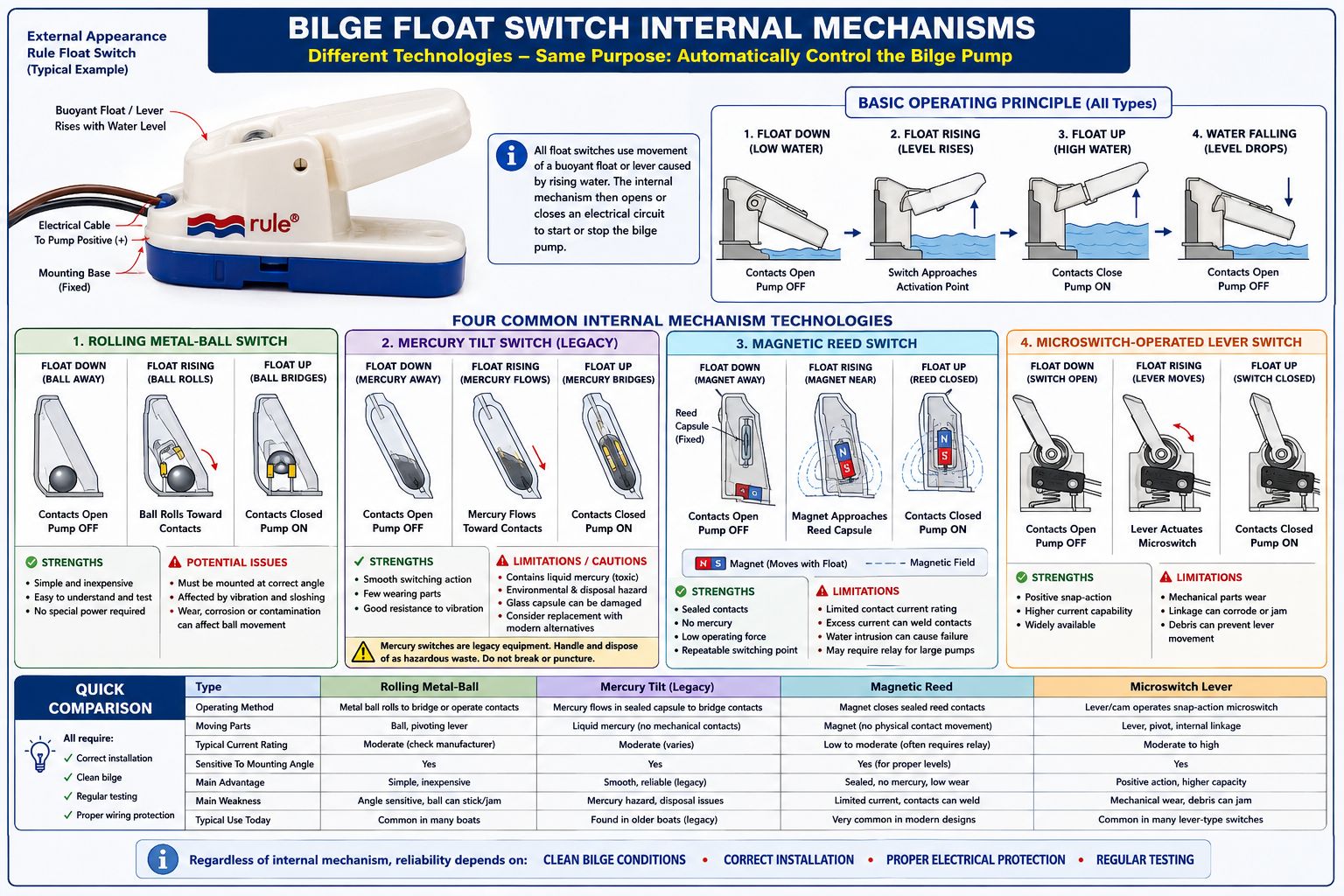
A bilge pump float switch is an automatic electrical control device that starts the bilge pump when water rises and stops the pump after the water level falls. Although the external switch may look similar from one model to another, the internal switching mechanism can differ considerably. The four common internal arrangements are:
- Rolling metal-ball switches
- Mercury-tilt switches
- Magnetic reed switches
- Microswitch switches
All three rely on movement of a buoyant float or lever, but they use different methods to open and close the pump circuit.
How
Different Bilge Pump Float Switches Work - Basic Operating Principle
A mechanical bilge float switch normally consists of a fixed mounting base and a buoyant lever or float body attached to a pivot. As bilge water rises, buoyancy lifts the moving section of the switch. The resulting angular movement operates an internal electrical contact. In a conventional automatic bilge-pump circuit:
- Float down: The electrical contacts are open and the pump is off.
- Float rising: The switch approaches its operating angle.
- Float up: The electrical contacts close and the pump starts.
- Water falling: The float drops until the contacts reopen and the pump stops.
The switch usually operates only on the positive side of the bilge-pump circuit. The pump negative conductor normally returns directly to the vessel’s DC negative switchboard bus. The float switch itself normally has two wires because it acts as an electrical contact inserted in series with the pump’s positive supply.
How
Different Bilge Pump Float Switches Work - Rolling Metal-Ball Float Switches
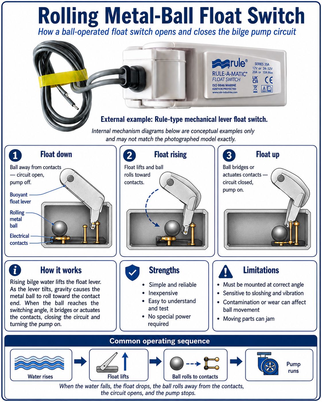
A rolling-ball float switch contains a conductive metal ball inside the moving float body or lever. The ball is free to roll along an internal track as the switch changes angle.
When the float is down, the ball rests at the lower end of the internal chamber and does not bridge the electrical contacts. The circuit therefore remains open.
As the bilge water rises, the float arm pivots upward. Once the arm reaches a predetermined angle, gravity causes the ball to roll toward a pair of fixed contacts. The ball touches or bridges those contacts, completing the electrical circuit and supplying power to the bilge pump.
When the water level falls, the arm rotates downward. The ball rolls away from the contacts, opening the circuit and stopping the pump.
Some designs use the ball to move a small internal contact mechanism rather than carrying the full pump current directly. The exact arrangement depends on the manufacturer.
Advantages. Rolling-ball switches are mechanically simple and inexpensive. They do not require a separate external power supply, and their operation can usually be tested by lifting the float manually. They are also relatively easy to understand, inspect and replace.
Limitations. The switch must normally be mounted in the correct orientation. If it is installed at the wrong angle, the ball may not roll consistently or may operate at an incorrect water level.
Wear, corrosion, contamination or deformation inside the switch can interfere with ball movement. Boat motion may also cause the ball to move repeatedly in rough conditions, resulting in intermittent pump cycling. A rolling-ball switch can therefore be affected by:
- Incorrect mounting angle
- Heavy vibration
- Bilge-water sloshing and vessel heel angles
- Internal wear and tear
- Contamination entering a damaged housing
- Corroded electrical contacts
A sealed switch should not normally admit bilge contamination, but a cracked housing, failed cable seal or worn pivot can eventually cause internal failure
How
Different Bilge Pump Float Switches Work - Mercury-Tilt Float Switches
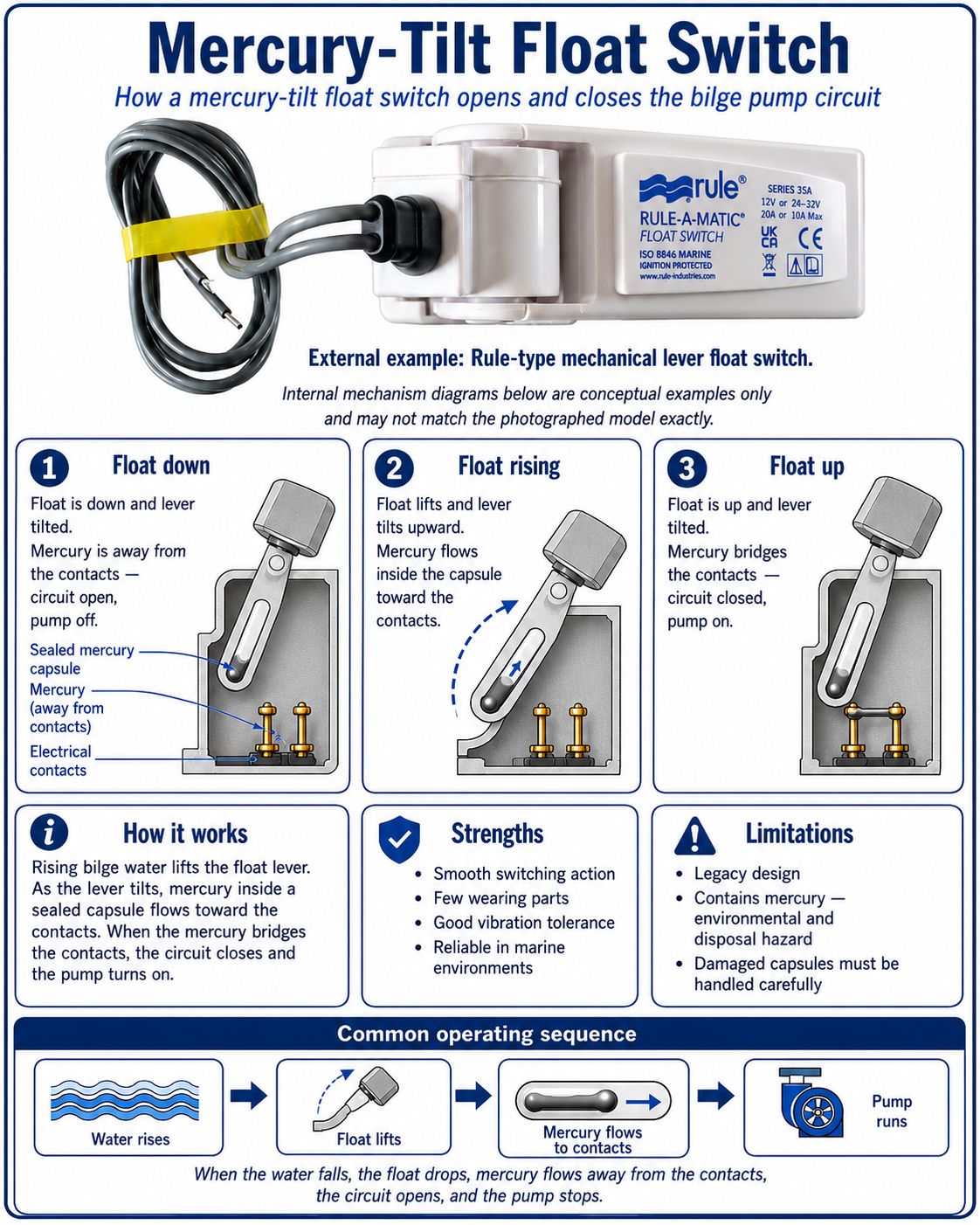
Mercury float switches use a small sealed glass or metal capsule containing liquid mercury and electrical contacts. The capsule is mounted inside the moving float or lever. Mercury is electrically conductive. As the switch tilts, the mercury flows from one end of the capsule to the other. With the float in the down position, the mercury remains away from the contact terminals. The circuit is open and the pump remains off.
As rising water lifts the float, the capsule tilts. At the operating angle, the mercury flows across the internal contacts and electrically connects them. The pump circuit closes and the pump starts. When the water falls, the capsule tilts back. The mercury flows away from the contacts, opening the circuit and stopping the pump. The movement is smooth because mercury is liquid and does not rely on a rolling solid part or conventional snap-action mechanism.
Advantages. Mercury switches historically offered several practical advantages:
- Few mechanically wearing internal parts
- Smooth switching action
- Reliable operation when correctly mounted
- Good resistance to vibration-induced contact bounce
- Long electrical contact life in a properly sealed capsule
The mercury itself forms the moving electrical contact, so there is no conventional contact arm repeatedly rubbing against another surface.
Limitations and Environmental concerns. Mercury is toxic and presents a serious environmental and disposal hazard if the sealed capsule is broken. For this reason, mercury switches are now largely regarded as legacy equipment and have been replaced in many applications by reed switches, electronic sensors and other non-mercury mechanisms.
An old mercury bilge switch should not be cut open, crushed or placed in ordinary waste. It should be handled as mercury-containing electrical equipment and disposed of through an appropriate hazardous-waste or recycling service. Other limitations include:
- Operation depends on correct mounting angle.
- The glass capsule can be damaged by severe impact.
- A cracked outer housing may expose the capsule to mechanical damage.
- Some older units may have degraded cable insulation or seals.
- Replacement with an equivalent modern switch may require checking current rating and activation height.
The presence of mercury does not automatically mean the switch is unsafe while intact, but damaged or obsolete units should be replaced carefully.
How
Different Bilge Pump Float Switches Work - Magnetic Reed Float Switches
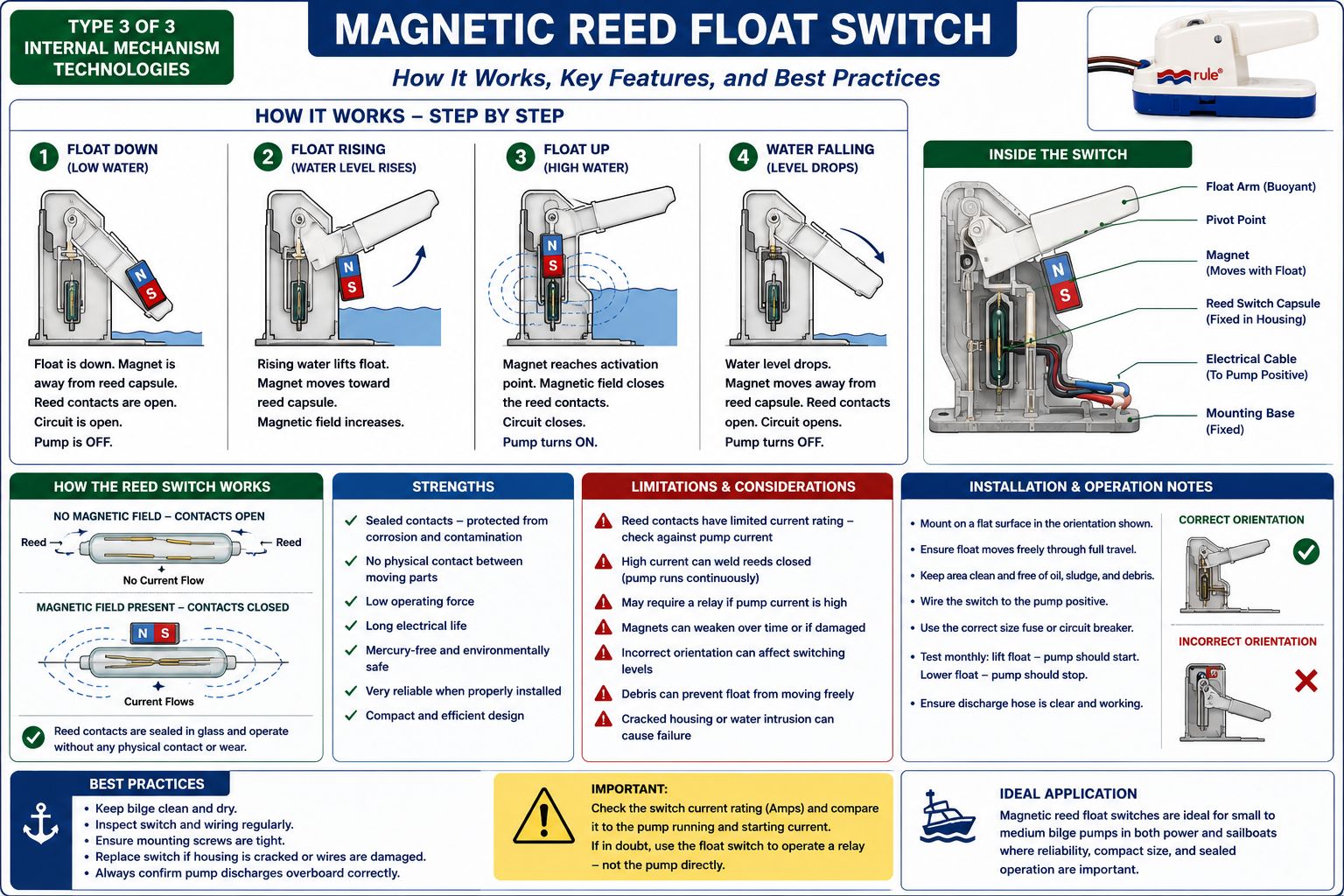
A magnetic reed switch uses a permanent magnet and a sealed reed contact. The reed switch itself is normally enclosed in a small glass capsule inside the fixed portion of the switch. The magnet moves with the float or lever.
What is a reed switch?
A reed switch contains two thin ferromagnetic metal blades, called reeds. The reeds are sealed inside a glass tube containing an inert atmosphere or vacuum. Without a magnetic field, the reeds remain separated in a normally open switch. When a magnet moves close enough, the magnetic field causes the reeds to attract each other and touch, closing the electrical circuit. When the magnet moves away, the reeds separate and the circuit opens.
How it works in a bilge float switch
The magnet is built into the buoyant float arm or moving float body. The reed capsule remains fixed inside the switch housing. As the bilge water rises:
- The float moves upward.
- The magnet approaches the reed switch.
- The magnetic field closes the reed contacts.
- The pump circuit is energised.
- The pump starts.
As the water level falls:
- The float moves downward.
- The magnet moves away from the reed capsule.
- The reed contacts open.
- The pump stops.
Some designs use more than one magnet or reed capsule to establish different turn-on and turn-off levels. Others use magnetic latching or electronic circuitry to increase the difference between the activation and deactivation heights.
Advantages. Reed switches have no exposed electrical contacts and require very little force to operate. The reed capsule is sealed from the surrounding atmosphere, which protects the contact surfaces from ordinary corrosion. Typical advantages include:
- Sealed electrical contacts
- Low mechanical operating force
- No mercury
- Repeatable switching point
- Compact construction
- Good resistance to environmental contamination when the housing remains intact
The magnet and reed switch do not need to touch physically. This reduces friction and mechanical wear within the electrical switching mechanism.
Limitations. Reed contacts are small and have a limited current rating. Some bilge float switches use reed contacts that can directly operate a small pump, while others should operate a relay rather than carrying the full pump current. Excessive current can weld the reed contacts together. A welded contact can cause the pump to run continuously. Other possible failures include:
- Cracked reed capsule
- Weakened or displaced magnet
- Water intrusion into the housing
- Contacts welded by excessive current
- Incorrect installation orientation
- Debris preventing float movement
- Damaged cable or corroded external connections
The switch’s published current rating must therefore be checked against the pump’s normal running current and starting or locked-rotor current. A relay may be appropriate where the pump current approaches the switch rating.
Microswitch-Operated
Float Switches
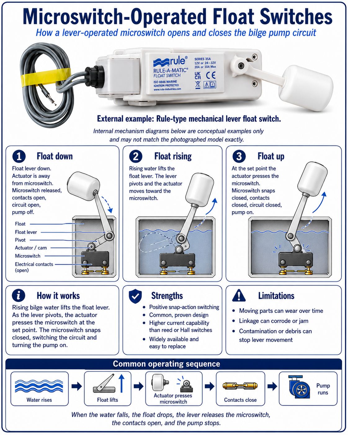
Although the three mechanisms above are commonly discussed, many lever-type float switches use a conventional snap-action microswitch. In this arrangement, the float lever does not directly carry the electrical contact. Instead, the lever operates a sealed or enclosed microswitch through a cam, plunger or linkage.
As the float rises, the linkage reaches the microswitch operating point. The microswitch snaps from open to closed and energises the pump. As the float falls, the mechanism releases and the switch returns to its original state. The snap action provides a definite change of state rather than allowing the contacts to close gradually.
Advantages include a positive switching action and relatively high current capability. Weaknesses include mechanical wear, pivot corrosion and possible failure of the internal linkage.
Standard
and Reverse Switching Action
Most bilge-pump float switches use standard action:
- Float down: contacts open
- Float up: contacts closed
This is described as normally open operation because the switch remains open when the bilge water is below the activation level. Some switches can be inverted, repositioned or internally configured for reverse action:
- Float down: contacts closed
- Float up: contacts open
Reverse action is used in specialised level-control applications but is not the usual arrangement for a standard bilge pump. The manufacturer’s wiring and mounting instructions must be followed because physically reversing a switch does not always produce a safe or reliable reverse action.
Why
Turn-On and Turn-Off Heights Differ
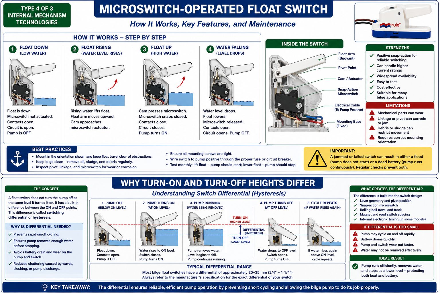
A float switch normally turns the pump on at a higher level than the level at which it turns the pump off. This difference is called switching differential or hysteresis.
The differential prevents rapid on-off cycling.
For example, the float may close the circuit after the water reaches the upper activation point. The pump then lowers the bilge level until the float reaches a lower release point. Only then does the switch reopen. Without sufficient differential, small waves or pump discharge returning through the hose could repeatedly start and stop the pump. The differential may be created by:
- The geometry of the lever arm
- A snap-action microswitch
- The travel of a rolling ball
- Magnet and reed-switch spacing
- Internal electronic timing
- Separate high and low sensing points
Bilge Pump Float Switches Work - Installation Considerations
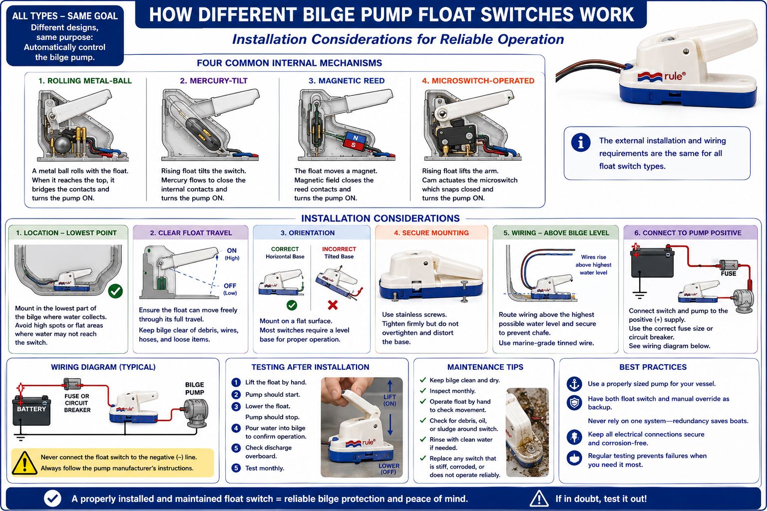
Regardless of the internal mechanism, the float switch must be installed where its moving section can travel freely. The switch should be:
- Mounted securely and level where required
- Oriented exactly as specified by the manufacturer
- Clear of hoses, wiring and structural obstructions
- Protected from cable ties, nuts, bolts and loose debris
- Positioned so the pump can remove water before the switch drops
- Kept away from excessive sloshing where practical
- Accessible for testing and replacement
Electrical joints should be made above the normal bilge-water level. Connections should use properly crimped, sealed marine terminals or heat-shrink connectors suitable for the cable size and current. The switch wiring must also be protected by the correctly rated fuse or circuit breaker.
How
Different Bilge Pump Float Switches Work - Maintenance and Testing
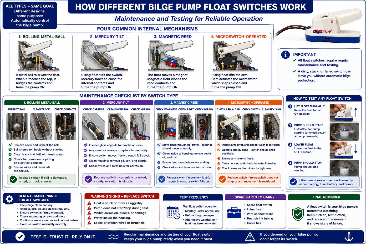
A float switch may appear simple, but its reliability depends heavily on bilge cleanliness. Oil, sludge, hair, cable clippings and general debris can prevent the float from rising or falling. A jammed switch may cause either failure mode:
- Jammed down: the pump does not start.
- Jammed up: the pump runs continuously.
The switch should be tested regularly by lifting the float through its full travel. The pump should start at the expected point and stop when the float is lowered. The test should also confirm that:
- The float moves freely.
- The mounting remains secure.
- The pump discharges water overboard.
- The manual override operates.
- The wiring is supported and undamaged.
- Electrical joints show no corrosion or heat damage.
- The discharge hose does not return excessive water to the bilge.
How Different Bilge Pump Float Switches Work - Switch Selection
How Different Bilge Pump Float Switches Work. A suitable bilge float switch must be selected according to more than its external shape. The important considerations include:
- Pump running and starting current
- Switch contact rating
- Bilge depth and available movement
- Expected contamination
- Vessel motion
- Required turn-on and turn-off heights
- Mounting orientation
- Access for inspection
- Compatibility with a relay or control panel
- Ignition-protection requirements where applicable
Mechanical and
Electrical Repairs Resource
LEARN EVERYTHING ABOUT ALL OF YOUR BOAT SYSTEMS! How Different Bilge Pump Float Switches Work! If you are headed somewhere remote consider the need to expand your knowledge base or have an information resource on board. Why not get a copy of my book The Marine Electrical and Electronics Bible 4th Edition. By and for yachties, with everything from batteries and charging, solar and wind, diesel engines and marine electronics and so much more. Your complete systems guide. 650 pages of practical advice. In Australia and New Zealand order a copy through Boat Books. UK and European boats can buy the UK Edition ORDER HERE. US and Canadian boats can get the US Edition ORDER HERE. Marine systems are my profession so let me help you. By a liveaboard boat owner for other boat owners



How Different Bilge Pump Float Switches Work
Rolling-ball and microswitch models remain common because they are simple and readily available. Reed-switch models offer sealed, low-force operation and avoid mercury. Mercury switches may still be found in older installations but are generally better treated as legacy components requiring careful replacement and disposal. The most important factor is not merely the internal switch type. Reliable operation depends on correct installation, adequate current rating, clean bilge conditions, protected wiring and regular functional testing.