Marine Electrical Courses Online Circuits
Marine Electrical Courses Online Circuits is all about understanding voltage, current and resistance. It is important to understand the nature of voltage, current and resistance. They are fundamental parts of design, and faultfinding simple electrical circuits. These are applied using Ohms Law and you must be able to understand and apply this Law as it is essential to making calculations and more importantly testing and troubleshooting your boat systems.
After completing this lesson unit you will
understand the definition of voltage; understand the definition of current; understand
the definition of resistance; understand Ohms Law and understand the definition
of Power. You will also understand how these apply to your typical boat
electrical circuits.
Marine Electrical Courses Online Circuits - Voltage
What is Voltage? Voltage is the unit of potential difference, electrical force, or "pressure" that will cause a current to flow in a circuit. Voltage is named after Alessandro Volta (1754-1827). A more formal definition is given as follows:
"The volt is the measure of the work required to move an electric charge. When 0.7376 foot pound of work is required to move 5.25 x 10^18 electrons between two points, each with its own charge, the potential difference is 1 volt. Potential difference is measured in Volts (V or E)." Another definition is that 1 volt is the amount of Electromotive Force (EMF) required to move 1 ampere of current through a resistance of 1 ohm.
The measurement units for voltage are:
1 millivolt = 1mV = 1/1000 V
1 volt = 1V= 1 volt
1 kilovolt = 1 kV = 1000 volts
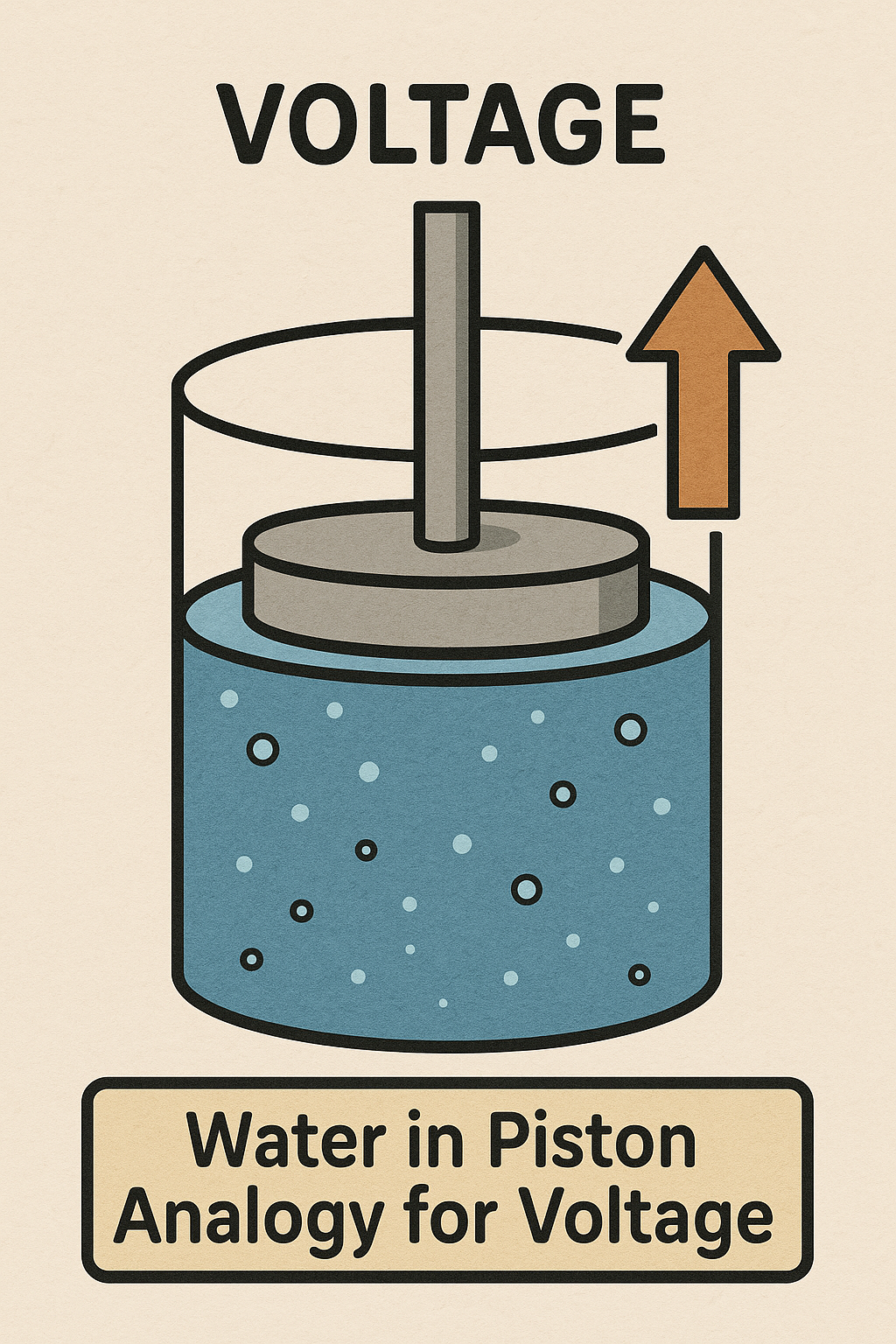
The Voltage Water Analogy
The water-in-piston analogy is a simple way to visualize how voltage works in an electrical circuit.
- The Piston: This represents the voltage source. Just as a piston applies pressure to water, a battery or power supply provides the electrical force that pushes electrons through a circuit.
- Water Pressure: Analogous to voltage, the pressure created by the piston determines how much force is available to push water through the system.
- Water Flow: This represents electrical current. Just as water moves through a pipe due to pressure, electric current flows through wires due to voltage.
- Resistance (Narrowed Pipe): If a pipe is constricted, it limits water flow—this is similar to a resistor in a circuit restricting current.
Voltage is like the force that pushes water (current) through a circuit, and resistance controls the flow. Just as a stronger piston applies more pressure, a higher voltage source pushes more charge through a circuit.
Imagine a water tank positioned above ground:
- The Water Tank – Represents the voltage source, like a battery or power supply.
- Height of the Tank – The higher the water tank, the greater the pressure (voltage) pushing water downward.
- Water Pipes – Similar to electrical wires, they carry water (current) from the tank to a destination.
- Flow Rate – Represents current. A bigger pipe allows more water to flow, just like a thicker wire allows more electric current.
- Valves (Resistors) – Placed in the pipes, they control the flow rate by restricting movement, much like resistors limit electric current.
So, voltage is the force pushing water down from the tank, just as electrical voltage pushes electrons through a circuit.
Marine Electrical Courses Online Circuits - Current
Current is the movement, motion or rate of flow of an electrical charge, or the
flow of free electrons through a conductor or circuit. One ampere of current is
one coulomb (6.25 x 10^18 6 million million million electrons) move past a
given point per second. To make current flow an Electromotive Force (EMF) is
required
The measurement units for current are:
1 milliampere = 1 mA = 1/1000 A
1 ampere = 1 amp = 1 A
1 kiloampere = 1 kA = 1000 amperes
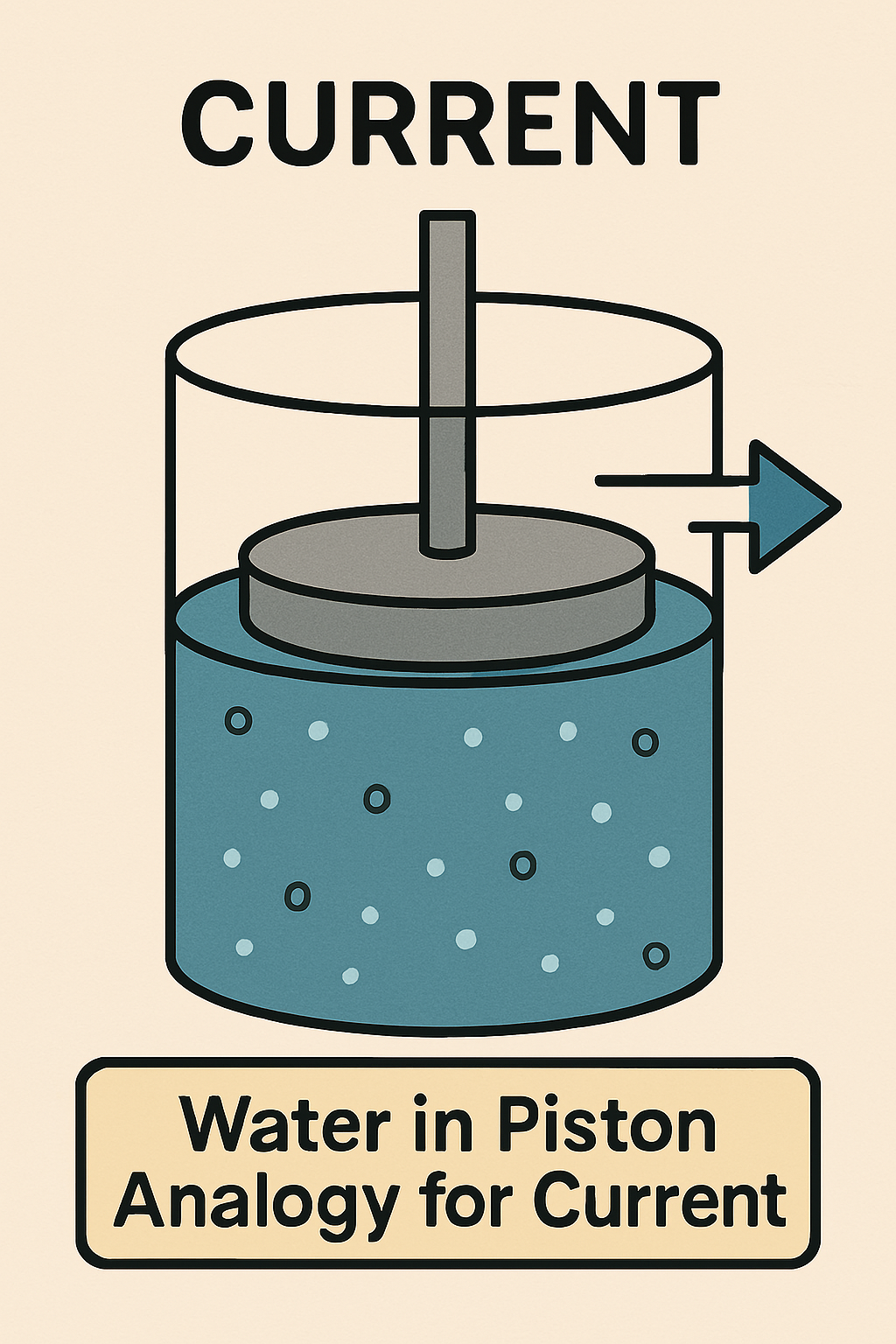
The Current Water Analogy
In the water-in-piston analogy for electrical current, the components represent key electrical concepts:
- The Piston – Acts like a pump that moves water, similar to how a voltage source drives electric current through a circuit.
- Water Flow – Represents the electric current, which is the movement of charge (electrons) through a conductor.
- Pipe or Channel – This symbolizes the wires in an electrical circuit, allowing the water (current) to flow smoothly.
- Resistance (Narrowed Section) – If there’s a restriction in the pipe, it represents resistance, which limits the flow of water—just like a resistor reduces current in a circuit.
- Pressure Difference – The pressure created by the piston equates to voltage, the force pushing electric charge through a circuit.
Marine Electrical Courses Online Circuits - Resistance
Resistance is the opposition or restriction to the flow of electrons in a DC conductor or circuit. It resists flow! All materials and parts of a circuit resist the flow of electrons and create or cause resistance. The movement of electrons through a circuit with resistance (or a resistor) will cause some of the electrical energy to convert to heat energy. The symbol used is the Greek symbol Omega and the unit of measurement is the Ohm. The term impedance is also used with respect to resistance in AC circuits and this is used commonly used with in electronics theory. It's measured in ohms (Ω), named after the German physicist Georg Simon Ohm. Resistance scale measurements in ohms are typically classified into different ranges, depending on the application.
Resistance Measurements
The measurement units for resistance are:
Very Low Resistance Milliohms (mΩ): (1 mΩ = 0.001 Ω). Used in applications where very low resistance is measured, such as in electrical contacts and conductive materials.
Low resistance (0 Ω to 1 kΩ): Found in conductive materials such as metals and used in applications like electrical wiring and power distribution.
Medium resistance (1 kΩ to 1 MΩ): Common in resistors used in electronic circuits for signal processing, voltage regulation, and filtering.
High resistance (1 MΩ to 1 GΩ): Used in components for insulation, high-impedance circuits, and electrostatic applications. Used commonly in insulation resistance testing.
Measuring resistance is done with a multi-meter, which has different scales for precise readings depending on the expected resistance ranges.
Conductor Parameters
There are 4 main
factors that affect the value of resistance in a conductor:
1. Resistivity of the material the conductor is made from, i.e. copper, silver
etc
2. Length of the conductor
3. Cross-Sectional Area of conductor, i.e wire size
4. Temperature of conductor
As the quantity of electron flow is dependent on how readily particular atoms
give up their electrons and accept new electrons, materials that allow this are
termed conductors. Copper, Silver and Aluminum are the best conductors.
Materials that do not give up electrons easily or which restrict the flow, are
called insulators. PVC, rubber, glass and porcelain are all good insulators.
Insulators are used to surround or cover conductors such as an insulated wire
Length. The longer the conductor is the greater the resistance.
Resistance is increased or decreased in proportion to the overall conductor
length. This is a key factor when considering long boat wiring runs.
Cross-Sectional Area. As the cross-sectional area of a conductor
increases, the resistance decreases, and vice versa. For example, if the area
of a conductor is doubled, the resistance is reduced by half.
Temperature. When the temperature
of a conductor increases, the resistance increases. The temperature factor is
not as predictable as the other factors, but it must be considered when dealing
with electrical circuits.
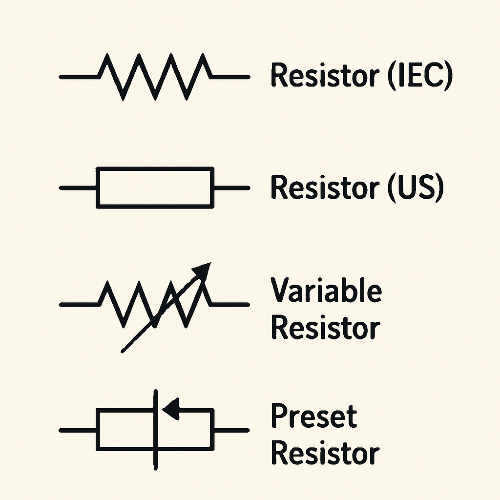
Resistance Symbols
The general symbols used in circuit diagrams or prints is the open rectangle or a zigzag line. It is easier to use the rectangle when making your own diagrams.
WHAT IS OHMS LAW?
The most fundamental relationship between
the three primary electrical characteristics of current, voltage and resistance
is Ohms Law. A German mathematician, George Simon Ohm, formulated this
relationship in the 19th century. Ohms Law states that current is directly
proportional to voltage and inversely proportional to resistance. If you know 2
of the 3 values the 3rd can be calculated.
Watts Divided by Volts = Amperes (amps)
Watts Divided by Amperes (amps) = Volts
Volts Divided by Amperes (amps) = Ohms
Volts Times Amperes (amps) = Watts
Examples
1. A circuit has a current of 4 amperes and resistance of 10 ohms. What is the
voltage?
If E = I x R, E (volts) = 4 amps x 10 ohms,
E = 40 Volts
2. A circuit has a voltage of 120 volts and resistance of 60 ohms. What is the current?
If I = E/R, I (amps) = 120 volts / 60 ohms, I = 2 amps
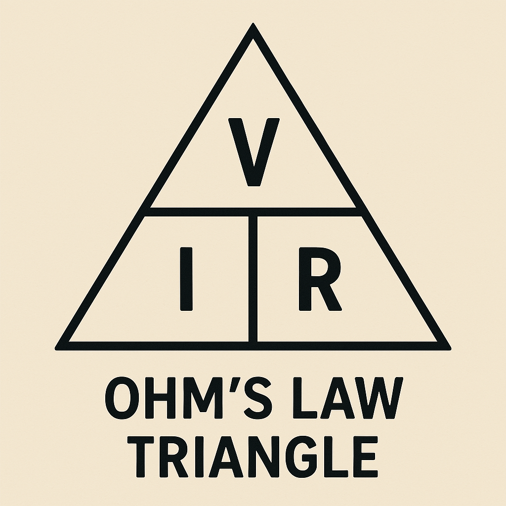
Ohms Law Triangle
The triangle makes calculating easy when
you struggle with this. To use the
triangle, place your finger over the unknown value to view the calculation
required.
Example
If the known resistance of 10 ohms, and the voltage is 13.8 volts across the
resistance and we need to know the current, place your finger over the I in the
triangle leaving V over R.
V / R = 13.8 / 10 = 1.38 Amps
Marine Electrical Courses Online Circuits - Power
The unit of electrical power is the watt (W). It is named after James Watt (1736 -1819). The definition is that one watt of power equals the work done in one second by one volt of potential difference in moving one coulomb of charge. It is the power expended when 1 ampere of direct current flows through 1 ohm of resistance. All resistive materials that conduct a current generate heat. It is also explained as the rate at which electrical energy is transferred or converted into another form, such as light, heat, or motion.
The Power Formula
The following formula uses Ohms Law parameters to calculate power. In some
cases nameplate data may express the power in watts and the current value is
required
P = V x I
P = I Squared/R
P = I Squared x R
With these equations it is possible to derive other formula to calculate the
voltage, current, resistance from any two known parameters.
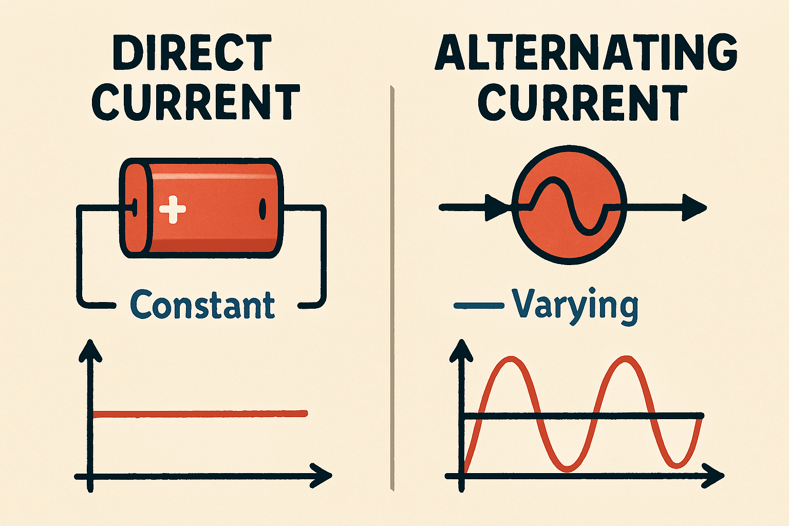
What is the difference between AC and DC?
AC is Alternating Current and one that reverses direction at regular intervals. Alternating Current is used at frequencies of 60 Hertz in the USA, 50 Hz in many other places in the world, and takes the form of a sine wave. It reverses direction every .0083 seconds. This will be covered in greater detail in the AC Module.
DC is Direct Current and one that flows in the same direction, either continuously, intermittently or pulsating.
Marine Electrical Courses Online Circuits is all about basics and makes life easier later.
