Sailboat Electrical System Design - Mapping, Protecting, and Understanding Your Marine Power System
Sailboat Electrical System Design. A cruising sailboat’s electrical system must support navigation, communications, dewatering, refrigeration, lighting, and domestic loads while preserving enough reserve for engine starting and essential safety functions. Designing a reliable electrical system begins with understanding how generation, storage, protection, and distribution are connected and how the system behaves when a charging source fails, a battery isolates, or a high‑current load starts. A yacht that appears reliable at the dock may still contain a single shared connection that disables several functions at anchor.
The foundation of good Sailboat Electrical System Design is a diagram of the yacht as it actually exists. Generic wiring diagrams hide the details that matter. A proper map shows every battery bank, alternator, solar or wind controller, hydrogenerator, shore charger, inverter, switch, fuse, busbar, and essential load. It also shows where these components are physically located, how DC and AC paths are separated, and which switches a crew member must find in poor light. This drawing becomes the reference for troubleshooting, upgrades, and emergency recovery.
Sailboat Electrical System Design - Map Loads Before Sizing Supply
Understanding loads is the next step. Essential loads such as bilge pumps, navigation lights, instruments, communications, and alarms must remain available even when part of the house system is unavailable. Domestic loads, refrigeration, water pumps, ventilation, cabin lighting, and device charging dominate daily consumption. High‑current loads such as the inverter, windlass, electric winches, thruster, or watermaker can overwhelm charging sources even with short use.
Each load should be measured or estimated for both current draw and operating time. Overnight consumption is particularly important because solar and hydro output may be minimal. A yacht that appears balanced during daylight may still reach a low battery level before dawn. Starting surge and voltage drop must also be considered; an inverter may demand high DC current even when its AC load appears modest. Identifying which loads must operate when a charging source or part of the house distribution is unavailable determines how circuits should be separated and how much reserve capacity is required.
Sailboat Electrical System Design - Regulatory
Compliance and Good Practice
A reliable sailboat electrical system must follow established marine wiring regulations rather than personal experimentation. Standards such as ABYC in North America and RCD/ISO requirements in Europe exist because they reflect decades of incident analysis, fault behaviour, and proven safety practice. Their guidance on conductor sizing, overcurrent protection, battery isolation, AC/DC separation, and earthing arrangements is designed specifically for the marine environment, where vibration, moisture, and confined spaces create risks not found in domestic or automotive systems. For that reason, avoid “creative” wiring solutions or improvised modifications simply because the system operates at 12 volts; low voltage does not mean low hazard, and incorrect wiring can still cause fire, equipment damage, or loss of essential functions. Unless marine electrical design is your professional expertise, follow published recommendations exactly and keep the system as simple and transparent as possible. Complexity increases the number of hidden failure points, makes troubleshooting harder, and often reduces reliability. A straightforward, standards‑compliant layout is easier to maintain, easier to explain to crew, and far more predictable under fault conditions.
Common Mistakes
When Ignoring Standards — What I See on Troubled Boats
As a marine electrical engineer, the same problems appear repeatedly on yachts where owners have ignored ABYC, ISO/RCD and manufacturer wiring standards. The most common issue is improvised wiring with circuits added without proper overcurrent protection, battery switches used as substitutes for fuses, and conductors sized by guesswork rather than by regulation. I frequently find shared negative paths that collapse under load, causing instruments to reset whenever a pump or windlass starts. Inverters are often connected with undersized cables that drop voltage so severely that the inverter shuts down even though the batteries are healthy. Many boats have charging sources combined through a single fuse or switch, so one failure silently disables alternator, solar and shore charging at the same time. AC systems are another recurring problem; incorrect neutral switching or poor isolation leaves outlets energised when owners believe they are safe, creating a serious shock hazard. Lithium installations are often the most concerning, with BMS disconnect behaviour not accounted for, leaving essential loads dead when the house bank shuts down. Almost all of these faults come from “DIY creativity” owners experimenting because the system is only 12 volts, but low voltage does not mean low risk. Fires, equipment damage and total loss of electrical function are common outcomes. When standards are followed, systems are predictable; when they are not, the boat becomes a collection of hidden failure points waiting to surface at the worst possible moment.
What a
Professional Checks First — Diagnostic Priorities on a Troubled Boat
When I step aboard a yacht with electrical problems, the first priority is to confirm the integrity of the main supply paths rather than chasing individual symptoms. I begin at the battery banks, checking their actual voltage under load and inspecting the condition of terminals, lugs, and busbars, because most failures originate from resistance, corrosion, or loose connections rather than from equipment. From there, I follow the negative return path to ensure it is not shared, undersized, or compromised, as a weak negative is one of the most common causes of instrument resets, pump surging, and inverter shutdowns. I then verify that overcurrent protection is present and correctly sized, looking for circuits that have been added without fuses or protected through battery switches instead of proper breakers. Charging sources are checked next, not at the controller but at the battery, to confirm that alternator, solar, wind, or shore chargers are delivering real current rather than just displaying reassuring lights. Finally, I examine AC and inverter isolation, because incorrect neutral switching or improvised transfer arrangements can leave circuits energised when owners believe they are safe. These initial checks usually reveal the underlying fault long before any equipment needs to be tested; most electrical failures come from architecture, not appliances.
First 10 Minutes
On Board — Diagnostic Workflow
- Battery Behaviour Under Load. The first check is always the batteries, but not their resting voltage and their behaviour under real load. A battery that looks healthy on a panel meter can collapse the moment a pump, windlass, or inverter draws current. Watching how the voltage responds under load immediately reveals whether the battery or its supply path is suspect.
- Main Terminations and Cable Condition. While observing the battery response, the next step is to inspect the main positive and negative terminations. A professional checks for loose lugs, corrosion, heat, and unsupported cables. Many faults originate here, and a quick physical inspection often exposes issues that instruments cannot.
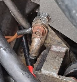
- Negative Return Path Integrity. The negative return path is examined next because a weak, corroded, or shared negative is responsible for a large proportion of intermittent electrical problems. Instrument resets, pump surging, and inverter shutdowns frequently trace back to a compromised negative path rather than a failed device. Most boats I attend have negative terminals such as in the image, and this sets up everything for failure.
- Overcurrent Protection and Circuit Additions. Attention then shifts to overcurrent protection. A professional looks for circuits added without fuses, oversized breakers, or battery switches being used as substitutes for proper protection. These improvised additions are common on DIY‑modified boats and often explain unpredictable system behaviour.
- Charging Sources Verified at the Battery. With the supply paths confirmed, charging sources are checked at the battery and not at the controller. Alternators, solar controllers, wind generators, and shore chargers often display reassuring lights even when delivering little or no current. Measuring at the battery reveals the truth.
- AC and Inverter Isolation. Finally, the AC and inverter isolation arrangement is reviewed. Incorrect neutral switching or miswired transfer arrangements can leave outlets energised when owners believe they are safe. This is a critical safety check and often uncovers faults that have gone unnoticed for years.
- System Drawings (or Lack Thereof). At this point, a professional asks for system drawings. In almost every case, none exist. The absence of documentation is one of the main reasons owners struggle to diagnose faults without a map, the system becomes guesswork.
Sailboat Electrical System Design - Keep Starting and House Functions Separate
Most cruising yachts separate the engine‑start supply from the house bank. The start battery must remain available for engine cranking, while the house bank supports continuous loads. The operational test is simple: domestic use must never leave the engine unable to start.
Normal and emergency switch positions should be drawn clearly. Shared negative connections, main fuses, or switches must be checked to ensure they cannot disable both banks simultaneously. If an emergency combine arrangement exists, it should be labelled and practised so the crew can operate it without unintentionally paralleling banks.
Sailboat Electrical System Design - Lithium Battery Considerations
Lithium installations require additional attention. The battery management system (BMS) controls charge and load paths and may disconnect the bank under fault conditions. The system drawing must show how the BMS interacts with chargers, alternators, and loads, and what happens if it disconnects. Essential loads and engine starting must remain available during a house‑bank shutdown. Charging equipment must be compatible with the bank and any BMS signals it requires.
Follow Each Charging Source to the Battery
Charging sources must be traced individually. Alternator, solar, wind, hydro, and shore charging do not simply combine at a battery terminal; each has its own regulator or controller, wiring, isolation, and protection. A shared fuse, switch, or BMS permission signal can disable multiple sources simultaneously.
Sailboat Electrical System Design - Engine Alternator
The alternator’s output depends on engine operation, belt condition, regulator behaviour, temperature, and the wiring between alternator and battery or busbar. A slipping belt, hot alternator, or poor connection can reduce charging long before the problem is obvious at the panel. The diagram should show the alternator’s full path, including any fuses, switches, combiners, or BMS signals that can interrupt its output.
Sailboat Electrical System Design - Solar Array
Solar charging depends on panel output, shading, controller behaviour, and wiring. Boom or sail shading, poor connections, or incorrect controller settings can all reduce effective charge. The solar path should be drawn from panel to controller to battery or busbar, with any shared components clearly marked so you can see where solar might stop if another part of the system fails.
Sailboat Electrical System Design - Wind and Hydro Generators
Wind and hydrogeneration depend on apparent wind or boat speed, but they share the same architectural concerns: controller behaviour, cabling, isolation, and protection. Their paths should be traced just as carefully as solar, with attention to any shared components that could disable them along with another source.
Sailboat Electrical System Design - Shore Charger
Shore charging depends on the incoming AC supply, the charger’s settings, and the DC wiring to the battery or busbar. If the charger shares a fuse, switch, controller, or BMS permission signal with another source, that dependency must be recorded. A single failure at that point can silently stop multiple charging sources at once.
Sailboat Electrical System Design - Verifying Actual Charging
When diagnosing poor charging, voltage must be measured at the battery as well as at the charger or controller. Resistance in wiring or connections can cause a substantial drop under load, leaving the battery at a lower voltage than the source reports. Actual charge current and battery response must be confirmed rather than relying on controller status lights, which indicate what the controller believes it is doing — not necessarily what the battery is receiving.
Protect and Distribute DC Power Correctly
DC distribution must be protected and arranged logically. High‑current cables normally reach protected distribution through switches and busbars, and branch circuits supply individual loads through appropriately rated protection. A fuse or breaker protects the circuit wiring, not the appliance, so its rating must suit the cable and installation.
Both positive and negative paths must be shown. A corroded negative busbar or return cable can disable several loads even when positive fuses remain intact. Busbars and terminations should be positioned where they can be inspected without exposure to bilge water or accidental contact with tools. Cables should be supported against movement and protected at bulkhead penetrations.
Essential functions such as bilge pumping, alarms, and communications may require supply paths that remain available when domestic circuits are switched off. Independence must be achieved without creating unprotected bypasses.
Separate Shore AC, Inverter AC, and DC
Shore power enters through a dedicated inlet and protection arrangement before supplying AC circuits and battery charging equipment. An inverter supplies selected AC loads from the battery, and an inverter/charger may pass incoming AC through to loads while charging.
The system drawing must show which outlets remain energised in each mode. Neutral switching, protective earth, and residual‑current protection require installation‑specific design. An inverter outlet may remain energised even when the yacht is unplugged from shore power, so isolation must be verified before work.
Continuous AC load must remain within the inverter’s rating and the DC bank’s ability to supply it. Heating appliances can drain battery energy far faster than a DC load schedule suggests.
Monitor System Performance Under Real Conditions
Voltage alone does not describe battery capacity or daily energy balance. Bank voltage, current, consumption, charging contribution, and alarms must be monitored using instruments appropriate to the battery type. Overnight discharge should be compared with charging recovered during the following day. Normal readings for each source should be recorded under known conditions.
High‑current connections should be inspected for heat, corrosion, and movement. A load that restarts when another load engages may indicate voltage drop or a poor connection. A no‑load voltage reading can conceal a fault that only appears under current.
Sailboat Electrical System Design - Design for Isolation and Recovery
A reliable electrical system is designed so a faulted branch can be isolated without disabling the entire yacht. Breakers, fuses, busbars, and battery switches must be labelled clearly. A current diagram must remain aboard and be updated after refits.
For each essential function, consider what happens if the house bank disconnects, the alternator stops, the solar controller fails, shore power is unavailable, or the main DC bus is damaged. Practical alternatives must exist where consequences warrant them — a handheld radio, manual bilge pump, or isolated engine‑start supply. These alternatives must be tested under controlled conditions.
FAQ — Sailboat
Electrical System Design
- Why do I need a diagram of my electrical system? Because the real installation always differs from assumptions. A proper diagram shows how batteries, charging sources, switches, fuses, busbars, and loads are actually connected. It reveals shared failure points, hidden dependencies, and unprotected circuits that only become obvious under load or fault. Without a diagram, troubleshooting becomes guesswork.
- How do I identify essential loads? Essential loads are those required for safety, dewatering, navigation, communications, and engine control. These loads must remain available even if part of the house system fails. Mapping them separately ensures they have reliable supply paths and appropriate protection, and that they are not accidentally disabled by domestic switching.
- Why must the start battery be separate from the house bank? The engine must always be able to crank, regardless of domestic use. If the house bank and start battery share a fuse, switch, or negative connection, a single failure can disable both. Clear separation ensures that lighting, refrigeration, or inverter use cannot leave the engine unable to start.
- How do I trace charging sources correctly? Each charging source, alternator, solar, wind, hydro, or shore charger must be traced from its regulator or controller to the battery or busbar. Shared fuses, switches, or BMS permission signals must be identified because a failure at any shared point can stop multiple charging sources at once. Tracing each path reveals these dependencies.
- Why does my battery stay low even when the charger shows normal output? Charging indicators show what the controller believes it is doing, not what the battery is receiving. Voltage drop in wiring or connections can reduce battery voltage under load, leaving the battery undercharged even when the controller reports normal operation. Measuring voltage and current at the battery is the only reliable way to confirm actual charging.
- Why is AC and inverter separation important? Shore AC and inverter AC must remain clearly isolated so the crew can tell which outlets are energised in each mode. Incorrect neutral switching or poor isolation can leave circuits live even when shore power is disconnected. Proper separation prevents accidental energisation and ensures correct protection and fault behaviour.
- How do I design the system for fault recovery? Every essential function must have an independent path or alternative. A manual bilge pump, handheld radio, or isolated engine‑start supply ensures the yacht remains operable even if the house bank disconnects or the main DC bus fails. These alternatives must be tested under controlled conditions so the crew knows they will work when needed.
- What is the most common cause of unexpected electrical failures? Shared failure points. A single fuse, switch, negative busbar, or BMS signal can silently disable multiple charging sources or battery banks. These shared points often go unnoticed until a fault occurs. A detailed system diagram is the only reliable way to identify and eliminate them.
- How often should I review my electrical system design? Review the system whenever equipment is added, batteries are replaced, charging sources are upgraded, or unexplained low‑battery events occur. Seasonal changes also matter: refrigeration loads rise in summer, and solar output falls in winter. Regular review keeps the system predictable and safe.
Your Complete
Onboard Repair Resource
Why not get a copy of my book The Marine Electrical and Electronics Bible 4th Edition. In Australia, New Zealand or Asia/Pacific order a copy through Boat Books, UK and European and Mediterranean based boats can Order Here. For US, Canadian and Caribbean based boats can get the US Edition here or at Amazon. Marine systems are my profession so let me help you.


FAQ — Common
Failure Scenarios in Sailboat Electrical Systems
- Why do multiple charging sources stop working at the same time? This usually happens because two or more charging sources share a single fuse, switch, negative connection, or BMS permission signal. When that shared point opens, even briefly the alternator, solar, wind, or shore charger may all stop simultaneously. The system diagram often reveals these hidden dependencies.
- Why does the battery show good voltage but still fail under load? A battery can display a healthy no‑load voltage while having insufficient capacity to support real loads. This is often caused by internal battery degradation or high resistance in cables, lugs, or busbars. The fault only appears when current flows, so testing under load is essential.
- Why does the inverter shut down even though the batteries appear full? Inverter shutdowns are commonly caused by voltage drop in the DC supply path. Undersized cables, corroded connections, or long cable runs reduce voltage at the inverter terminals during high‑current demand. The inverter sees a low voltage and disconnects, even if the battery itself is healthy.
- Why do instruments or navigation systems reset when another load starts? This is a classic symptom of a shared negative or a weak return path. When a high‑current load such as a windlass or pump engages, the voltage on the shared return drops momentarily, causing sensitive electronics to reset. The issue is rarely the device itself it is almost always wiring or busbar condition.
- Why does the alternator produce less charge than expected? Alternator output often falls due to belt slip, regulator temperature limits, poor wiring, or voltage drop between alternator and battery. The alternator may show normal output at the regulator, but the battery receives less due to resistance in the charging path. Measuring at the battery under load confirms the real output.
- Why does solar charging appear normal but the battery remains low? Solar controllers report panel voltage and theoretical output, not necessarily what reaches the battery. Shading, poor connections, incorrect settings, or shared fuses can reduce actual charging. A controller’s “charging” light does not guarantee the battery is receiving meaningful current.
- Why do AC outlets behave unpredictably when switching between shore power and inverter? This usually results from incorrect neutral switching or incomplete isolation between shore AC and inverter AC. If the transfer arrangement is unclear or miswired, outlets may remain energised unexpectedly or fail to energise when expected. Proper AC separation prevents these behaviours.
- Why does the BMS disconnect unexpectedly on a lithium system? A BMS disconnects when it detects over‑current, over‑voltage, under‑voltage, or temperature faults. If essential loads or charging sources depend on the house bank, a disconnect can shut down large parts of the system. The design must ensure that critical functions remain available even during a BMS‑initiated shutdown.
- Why do bilge pumps or alarms fail during a domestic power issue? This happens when essential loads are fed from the same distribution path as domestic circuits. If a main switch, fuse, or busbar fails, both domestic and essential loads may be lost. Proper system design keeps essential loads on independent, protected supply paths.
- Why does the system behave differently at anchor than at the dock? At the dock, shore power masks weaknesses in charging, wiring, and battery condition. At anchor, the system relies entirely on alternator, solar, wind, or hydro. Any shared failure point, voltage drop, or undersized wiring becomes obvious when charging sources are limited and loads run continuously.
What to Check
Before Calling an Electrician — Owner Checklist
1. Battery Condition and Behaviour. Check the battery voltage under load, not just at rest. A battery can look healthy until a pump, windlass, or inverter demands current. If voltage collapses when a load starts, the battery or its connections are suspect.
2. Main Terminals and Negative Return Path. Inspect the battery terminals, busbars, and negative return points for loose lugs, corrosion, or signs of heat. A weak or shared negative is one of the most common causes of resets, surging pumps, and inverter shutdowns.
3. Battery Switch Positions. Confirm that all battery switches are in their intended positions. Accidental isolation is surprisingly common, especially after maintenance or when crew unfamiliar with the system have operated switches.
4. Fuses and Breakers. Check the main fuses and breakers, particularly those protecting charging sources and high‑current circuits. A single blown fuse can disable alternator, solar, or shore charging simultaneously.
5. Charging Sources. If charging seems abnormal, verify that the alternator belt is intact and tensioned. Check solar controllers and shore chargers to ensure they are delivering actual current to the battery rather than simply displaying status lights.
6. AC and Inverter Source Selection. Confirm whether the boat is connected to shore power and whether the inverter is switched on or off. Many AC faults come from incorrect assumptions about which source is energising the outlets.
7. Recent Changes or DIY Additions. Think about anything that has been modified recently a new appliance, battery replacement, or DIY wiring addition. Most electrical problems begin immediately after something has been changed. My first questions is always “What were you doing when it failed or when inoperative” and I call it the fingers question.
Sailboat Electrical System Design Summary
A sailboat electrical system is a chain of loads, generation, storage, control, protection, and distribution. Designing it begins with understanding real consumption and required reserve, tracing every charging source to the battery, mapping every essential load through its protection and return path, and documenting shared points that could disable multiple functions. A well‑designed system remains reliable under load, predictable under fault, and recoverable when one source or bank becomes unavailable. Sailboat Electrical System Design for all you need to know.