Marine Electrical Courses Online Basic Circuits
Marine Electrical Courses Online Basic Circuits is all about understanding the basic theory of electrical circuits. It is essential in understanding how various circuit elements will be used and how they will be configured. It is important to also understand how to make basic instrument tests. In all cases you are testing or verifying one of these parameters
After completing this lesson unit you will understand the simple theory of series circuits; understand the theory of parallel circuits; understand the theory of basic electrical circuits; understand the use of circuit diagram notations and symbols and understand how to use a test instrument. To quote the Borg, “Resistance is Futile!”
Marine Electrical Courses Online Basic Circuits - Series
Circuits.
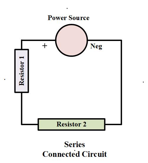
A series circuit is one where all of the
loads are connected end to end in a single daisy chain network.
R1 + R2 + R3 = R
In a series circuit there is only ONE path for the electricity to flow. If this
circuit was a string of light bulbs, and one blew out, the remaining bulbs
would turn off. In a typical boat circuit most are series circuits as the
diagram shows.
Typical series circuits in a boat are the engine starting system, the alternator charging system, power supplies to pumps, and other devices. I will follow up later on how to improve redundancy in these circuits as any single point failure will fail the device.
Marine Electrical Courses Online Basic Circuits - Parallel Circuit
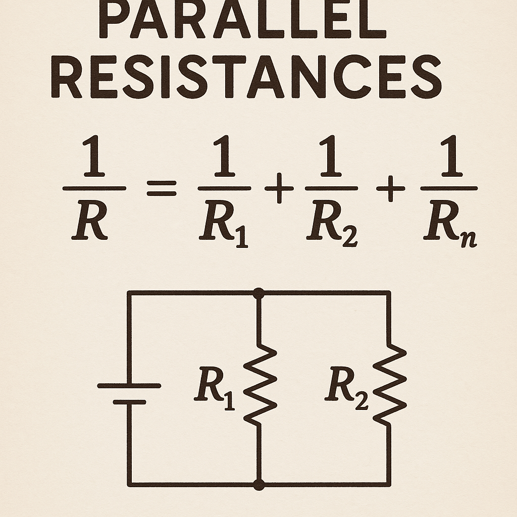
A parallel circuit consists of two or more paths for
the electricity to flow in. This means that the loads or resistances are
connected in parallel with each other. The loads are usually represented by
resistor symbols. If the loads are lamps in a typical cabin lighting system,
when one lamp element blows the other will remain operational. This is because
there is still a direct electrical path from the positive supply to negative
terminals.
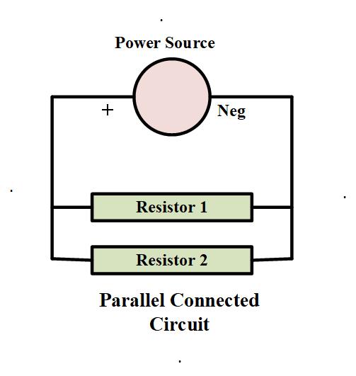
Parallel Circuits
Typical parallel circuits in a boat are often the lighting systems. There are generally no single point failures in these circuits, if one light fails the others remain in operation.
Marine Electrical Courses Online Basic Circuits - Combination
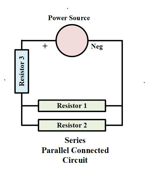
Many circuits consist of a combination of both series and parallel circuit resistances. When calculating circuit resistances and voltage drops they will need to be considered differently. In practical circuits two lights in a circuit are connected in parallel and the cable resistance supply both is a series resistance.
What is a Simple or Basic Electrical Circuit?
Most electrical circuits are basically the
same. Every electrical circuit can be divided into functional blocks. This is a
good practice when considering any circuit.
1. The Power Source or Supply. This may be a battery, alternator, solar
panel and so on.2. The Current Path. This may be the conductor, wire or cable, and can be also a
switchboard busbar. This is essentially a resistance.
3. The Load. This may be a lamp, a pump motor, or other connected device. This is essentially a resistance.
4. The Control or Protection Device. This is usually a switch to isolate power to the circuit or open the circuit and stop electron flow. This will make the circuit Open Circuit or Closed Circuit.
5.
The Status Indicator. This might be a lamp, or a voltmeter. More modern devices incorporate voltmeter and
ammeter. An ammeter is connected in series (through a parallel connected shunt)
to show the amount of current flowing in the circuit. Many circuits do not have
indicators and they are optional depending on the application, such as a
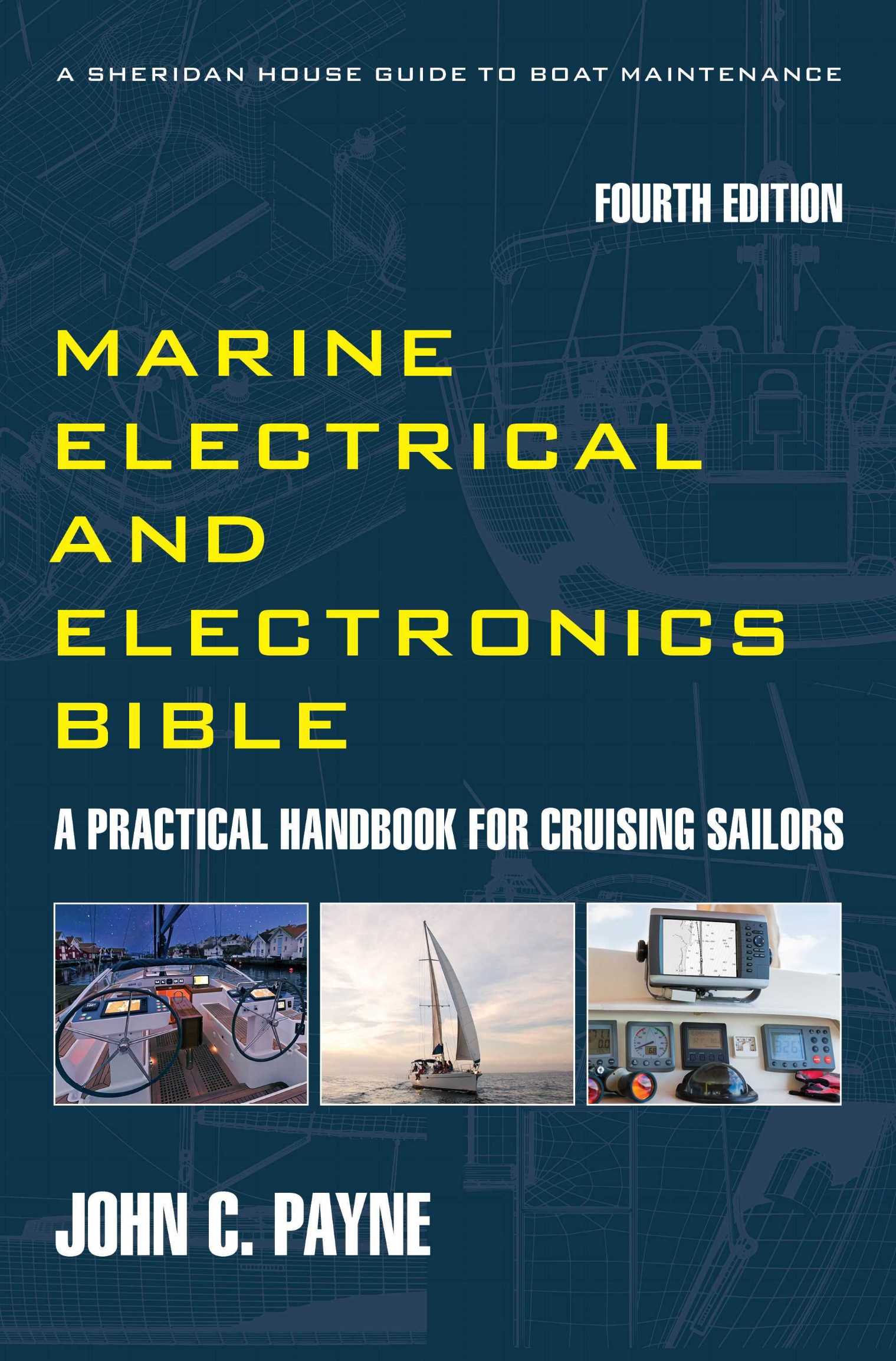
charging circuit or main switchboard. The Marine Electrical and Electronics Bible 4th Edition is here. Marine Electrical Courses Online Basic Circuits are part of every system.
Simple Electrical Circuit Analogy
Another example of a simple DC circuit is that of a
flashlight. The batteries in the flashlight provide the DC voltage source. The
inside of the battery case often acts as the negative circuit conductor. The
lamp bulb is the load and is essentially a resistor that heats up to emit
light.
The flashlight has an ON and OFF switch. This controls the flow of electricity.
Because there must always be a complete path for current to flow, the switch
stops the flow when it is in the OFF position. When the switch is ON, the
circuit is complete and current flows, lighting the bulb.
When the batteries run down the bulb gets dimmer as the electromotive force
from the battery reduces and there is less current flow. If the switch or other
part of the circuit is loose or makes poor contact, such as at the battery
terminals, the bulb will not work as the circuit opens. The usual “repair”
method is to tap the flashlight several times as we have all experienced to get
back the contact.
Circuit Contact Resistance Explainer
This is a key takeaway. All electrical circuits contain resistance at terminations or connection points, the poorer the contact the higher the resistance. This is known as contact resistance, other names are also interface resistance or transitional resistance. Another often used term for this is also parasitic resistance.
The sources for this are contact surfaces in switches, especially ones that have arced during operation. Every action on switches and relays results in small arcs or sparks. During operation they may have developed oxidizing surface layers. All switches, circuit breakers, relay contacts, connectors and terminals and your meter probes are subject to this. Values are typically quite low and are measured in the microohm to milliohm rang, until the contact point degrades. This is known as resistance creep. This is due to mechanical processes that include slowly weakening terminal torques often induced by vibration. Alternators and diesel engine starter motors and the related heavy current connections are a prime example. In many cases moisture can infiltrate terminations and create galvanic cells. For example a typical tinned copped ring connector may be fastened to a stainless terminal or a nickel coated one, and the cell degrades the connection and creates a high resistance
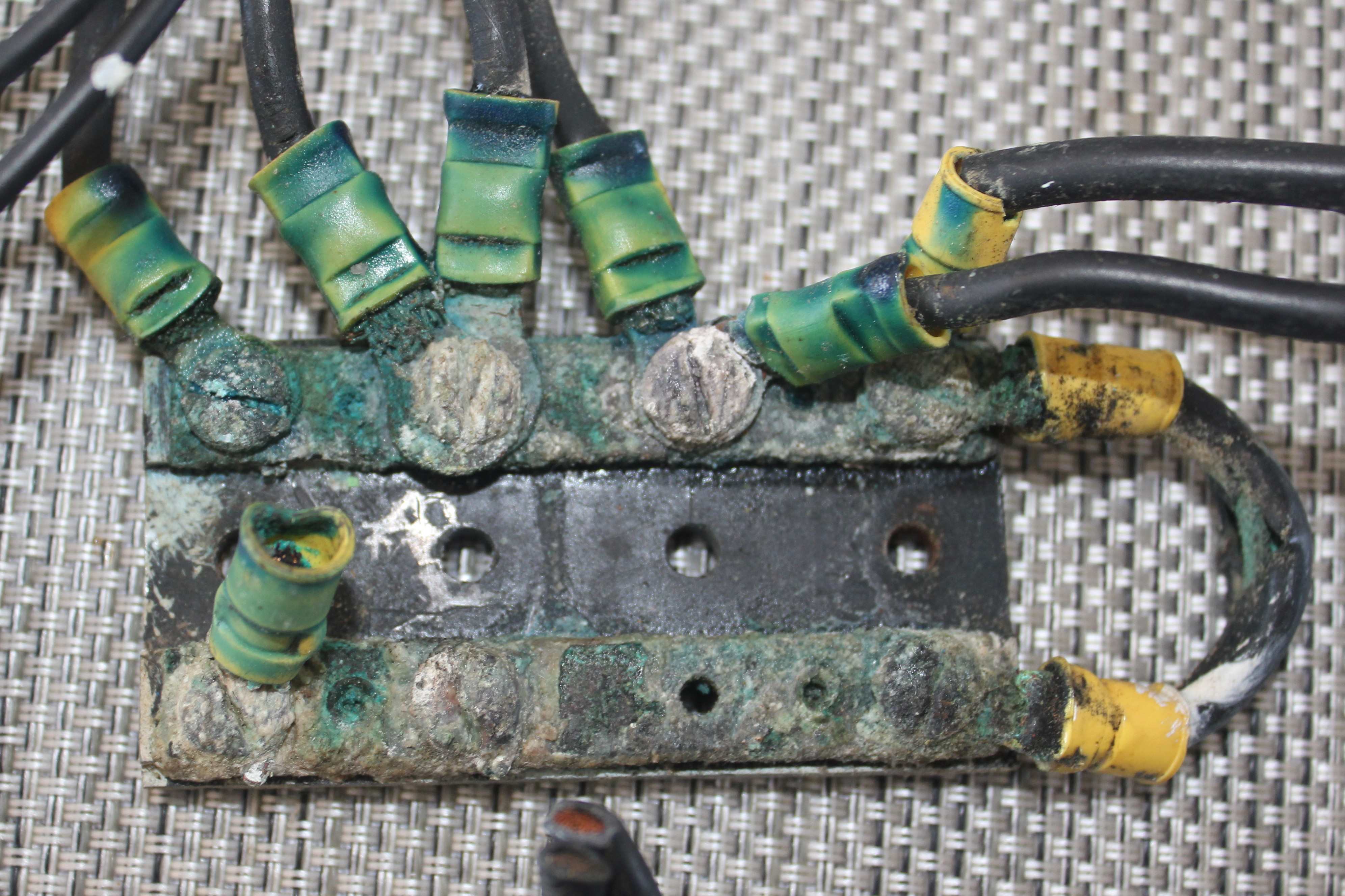
The result of higher contact resistance are voltage drops and when higher currents are passed this creates a heating effect. Contact resistance is a series resistance with the intrinsic resistance of conductors.
The image below shows what happens when connections degrade, higher resistances result. This was in a bonding system and the damage done was very extensive.
Practical
Exercise
On your own boat, turn over the engine and then stop it. If it is hard to start then even better. Immediately place your fingers on the main terminals of the starter motor after stopping. They will often be warm or even hot to touch if a high resistance is present. When you start a diesel engine a momentary current spike up to 500 amps will pass then possibly down to 60 A plus for a couple of seconds across the termination. This reduces the voltage and current to your starter and inhibits easy starting of the engine.
MAINTENANCE TIP. Every 6 months carefully removed the main cables terminals, both positive and negative, check they are clean and shiny. Replace and torque them up correctly. They should have a spring washer to maintain tension. This is one of my most common resistance related troubleshooting issues. Marine Electrical Courses Online Basic Circuits.
