Boat Risk Assessment
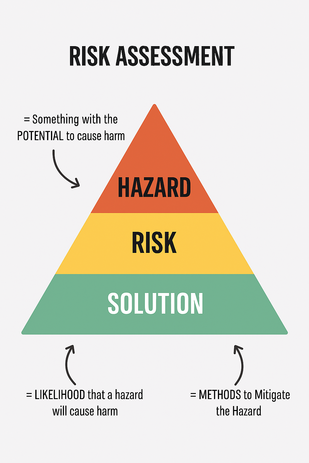
A boat risk assessment is somewhat of an alien concept for many boat owners. It shouldn’t be and given the average person performs many risk assessments every day, whether driving the vehicle, walking across a road, working in the kitchen or garden and so on. Risk assessments take place in every walk of life, from project and maintenance management to the financial world, from medical to industrial it happens all the time.
What is a risk assessment? A risk assessment is the systematic analysis of determining all the possible or likely negative events or scenarios; the probability of these event occurring; the potential consequences when they do occur; and then the tolerance or ability to withstand such events. What follows the outcomes of this analysis are the identification of the risk factors and measures to eliminate, control or mitigate them.
FMEA and Boat Risk
Assessment
A sailboat is relatively complex installation comprising many interdependent systems and elements. Given the safety implications I am surprised at how few ever perform a risk assessment. Several years ago I made a presentation to one of the ARC Rally Seminars. Over the past few years, apart from cruising yacht electrical and marine engineering systems, I have been actively involved in many new large commercial ship and oil rig construction projects. Before we commission a new vessel or even start to build and then commission the installation, we perform what is called a Failure Mode and Effects Analysis (FMEA) and then perform extensive testing and trials to prove and verify the conclusions. These days large projects have templates and software to facilitate this process. I should acknowledge that Risk Assessment (RA) or analysis and an FMEA differ in that one looks at risk and the other at failure modes. An RA is a top-down approach, which commences at a hazardous event. The FMEA is a bottom-up process, where an existing design is analyzed for possible consequences (effect) in the event of a failure
FMEA and Boat Risk
Assessment
After delivering a few lectures and receiving many emails from many boat owners, and witnessing the same system and equipment failures, I decided that the same principles could easily be adapted to smaller vessels, in particular cruising yachts. This exercise isn't as difficult as the name suggests. Essentially it entails the analysis of the boats starting and charging systems, as both are critical to propulsion or electrical power generation as well as the boat primary power system. You can easily extend this to every part of your boat, from the rigging and steering to the instrumentation and so on. When you perform an FMEA on your boat systems, you break each system down as far as is practicable, looking at possible and probable failure modes; single point failure points; root causes of failures; criticality of failures; pre-failure indication; the probability of failures and the consequential effects. This article is extracted from my book The Marine Electrical and Electronics Bible 4th Edition.
FMEA and Boat Risk
Assessment
As described above the Failure Mode and Effects Analysis (FMEA) is a systematic analysis of all the potential failure modes that can feasibly occur. Once this is carried out then corrective or mitigating actions can be implemented so as to reduce these failures. This methodical exercise enables a cause and effect of potential failures to be studied. The primary function of the exercise is the analysis of the systems and identification of any single point failures. In simple terms this means looking at what can happen in a worst-case situation. It is a fact that in most cruising yachts there is little or virtually no redundancy on any of the primary systems. It is necessary to first identify all of the points that upon failure will also fail the entire system, and then devise suitable methods and strategies to improve reliability and provide some redundancy.
FMEA and Boat Risk
Assessment
It is important when assessing the failure risks to consider the following factors and statistics:
Battery Power Supply. A failure in the battery system results in no power to electrical equipment. This can include a battery dedicated to starting the diesel engine. This can be further complicated with LiFePo batteries and the associated Battery Management Systems (BMS).
Battery Charging. A failure in the battery charging system means no charging of batteries and therefore an eventual loss of all electrical power, and possibly propulsion engine starting, loss of communications, navigation instruments etc. All this from a failure of an alternator or a component within the alternator. This also can be further complicated with LiFePo batteries and the associated Battery Management Systems (BMS).
Engine Starting Systems. A failure in the engine starting system means no propulsion and no charging of batteries, and eventual loss of all electrical power. A simple failure of a solenoid can lead to loss of propulsion and electrical charging.
Electrical Circuits. Approximately 80% of all electrical system circuit failures are due to faulty or failed electrical connections.
Equipment Installation. Approximately 70% of equipment and machinery failures are attributable to poor or improper installation, and to a lesser degree poor maintenance procedures.
Boat Battery Charging System FMEA
In general most people look at the boat battery charging system in terms of a series of discrete components. A charging system must not be viewed as a collection of components, but as an entire electrical power supply system, the boats power station or onboard electricity utility. Always take a holistic approach to the system and this will pay divedends when troubleshooting.
The typical charging system comprises a considerable number of elements and these are summarized below. Make a simple drawing if you do not have one on board. It is a good idea to trace out each circuit on your boat, and draw in each component and mark each connection on it.
Boat
Charging System FMEA
As a minimum the average electrical circuit will have 4 main positive circuit connections, 4 main negative circuit connections, 4 control circuit connections, possibly 2 changeover switch contacts, possibly a meter shunt, the engine alternator, the alternator regulator and the batteries that are charged, which might include startinga nd hosue or services batteries.
The Alternator. This includes several integral components such as the brushes, brush holders, sliprings, bearings, diodes and stator windings. Each can fail and the most common is bearing failure on the drive end, due to over tensioned or under tensioned rubber drive belts. It is also important to note that auxiliary terminals on an alternator are crucil and if damaged, loose or broken the alternator will not function.
The Regulator. This may be integral to the alternator or separate, as often is the case with fastcharge regulators.
The DC Positive Circuit. This includes the connections at the alternator and at the battery, and the changeover switch or isolation switch and diode or other charge distribution devices. Any one malfunction will prevent charging.
The DC Negative Circuit. This includes the connections at the alternator and battery, the cable back to the battery, and the meter shunt if fitted. In addition the engine block also in many cases becomes part of the negative circuit, along with alternator bracket, holding bolts and so on. Each connection will add a small amount of resistance to a circuit.
The Batteries. This includes the engine start battery and the house power batteries. Low battery voltage will mean hard engine starting. This is interconnected with charging systems.
Boat
Charging System FMEA
The math of this simple analysis is that there is an average total of 14 connection points plus the alternator, regulator and battery that can directly impact on the starting system, plus the human element, the “boat owner”. Each point represents a single point failure with subsequent total system failure, with no apparent redundancy. For this exercise wind, water and solar panels are considered extra or supplementary charge sources, as are diesel generators with AC battery chargers. These however can be factored into the redundancy provisions. The operational factors also must be considered, the human factor in particular. If a battery changeover switch is opened or fails during operation, the alternator can be destroyed, and it is more common than one might think. Boat charging systems are mission critical so look at making them robust and resilient.


