Boat Electrical Wiring
The boat electrical wiring has many elements and these ones are very important, all must be properly installed to avoid failure of the system. All the information is detailed in my book the Marine Electrical and Electronics Bible, 4th Edition. Get your copy here.
About Connectors and Terminations. These are electromechanical devices for joining two electrical parts such as a cable and terminal block. There are strip terminals commonly known as chocolate blocks, and screw terminals are used extensively. In boats a section of the block is cut off and used to terminate the wires. Careful insertion of wires is required, no over twisting of strands to prevent damage and proper insertion to the terminal without having a stray wire strand left out. In boats where the wire diameter is relatively small in relation to the screw overtightening can damage or cut through the wire strands. In many cases ferrules can be crimpted to the wire end before insertion. Other commonly used screw connectors are what are called BP connectors or acorns are also used ashore. These are insulated single screw connectors and you gently twist the strands together, insert and tighten. It is possible to also damage multistrand wires, in shore installations stranding is much less than in many marine cables. In practice I run a circuit without a single splice or joint in the circuit except at the device it powers up. I know people do this to join up shorter lengths of cables but this is a false economy and sets up the circuit for failures.
Boat Electrical Wiring
About Wire Soldering. Wires should never be soldered prior to insertion into screw type terminals as the softmetal will cold flow and often result in a loose and high resistance joint creating a fire hazard. The most common fault is under tightening and when they loosen also create a high resistance and heating can create a fire hazard. The ABYC standards (E-11.16.3.7) state that "Solder shall not be the sole means of mechanical connection in any circuit". I keep getting asked by people how to properly solder wires and I get a confused response when I state that I don’t have any solder joints and in fact commercial shipping doesn’t either. I am perplexed as to how this false narrative ever got oxygen and its hard to dispel. One marine electrical course I know includes a session on practicing soldering techniques.
Boat Electrical Wiring
Butt Connectors. These are commonly used and include shrinkable types, and many use regular types and slide some heat shrink tubing over the joint. The commonly observed practice of soldering wires first is not allowed under ABYC standards.
Twist on Wire Nuts. These are also known as Marrette wire connectors. These are not allowed by the ABYC in marine installations. ABYC E11.14.5.6 “twist on connectors, i.e., wire nuts, shall not be used”. To explain they are designed for use on single strand wire in shoreside domestic wiring installations. Boat wiring is multi-strand and when the wires strands are twisted together they are damaged and metal fatigue often break strands which reduces current carry capacity.
Boat Electrical Wiring
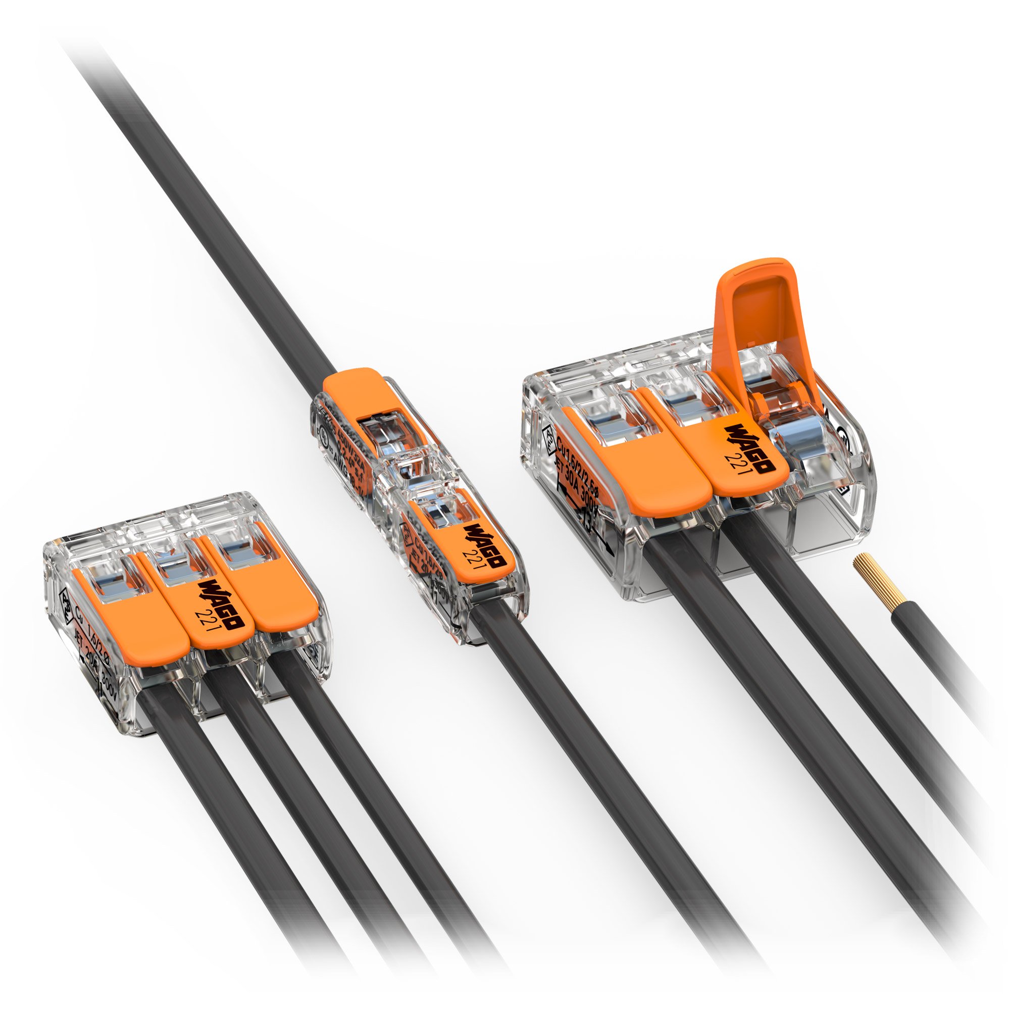
Wago Connectors. These are lever type connectors. I have used these German manufactured Wago connectors on everything on board during my rewire. They are very simple to use, do not require tools such a screwdriver, they do not damage the cable strands, they are also easy to disconnect when troubleshooting. They are suitable for all conductor types to 4mm, can combine different conductor types and sizes and have a high current capacity. There also heavier current capacity units for up to 6mm cables. They also have the Gelbox moisture protection which is fastened over the termination and has IPX8 level of protection. This means it can handle submergence in 1 metre of water for up 30 minutes which is ideal for bilge pump connections. I also used 5 terminal units to connect all my lighting circuit spurs above my headliner
Boat Electrical Wiring
Crimp Terminals. At the switchboard end of the circuit crimp terminals are the best solution. These require a crimping tool to compress the contact to hold the wire in place. Make sure that the ring size matches the stud or screw or retaining bolt size. A common error is to put oversized ones on and the contact quality is then degraded.
Boat Electrical Wiring
The Equipment and Switch Panel Termination. At the switchboard end or the device always allow a significant amount of extra cable. You can simply coil and fasten up when done. It allows sufficient cable to properly terminate. The same goes for the switch panel. I have seen some beautiful and meticulous wiring but there is absolutely no cable slack at all and this sets you up for troubleshooting access issues. You can have slack and still make it look neat and tidy.
Boat Electrical Wiring
The Cable Identification. At the switchboard end start with application of a number either slide on or wrap around once the terminal has been applied. This number should correspond to the one in your basic wiring plan and also for the circuit breaker number. You also should apply the same on each conductor at the equipment end such as a water pump or other device. You can use a permanent marker to also write the circuit name on the white outer sheath. Making your wiring schematic diagram should be done at the same time as you complete each wire installation. This is highly recommended. So much to learn about wiring a boat.

